In May 2019 I started working on the Record Clock Redux project and I actually completed the code, milled out the acrylic backplate and genuine 7″ single record all ready to assemble into the final clock. However, things happened and it never got finished, in fact I have barely touched a soldering iron, or done anything PIC micro related since.
Anyway, I sat in the workshop in the middle of December 2021 and put the pieces on the workbench. I looked over them trying to recall how I’d intended it to fit together and I decided this was the time (pun intended) to finish “Record Clock Redux“.
Final Assembly
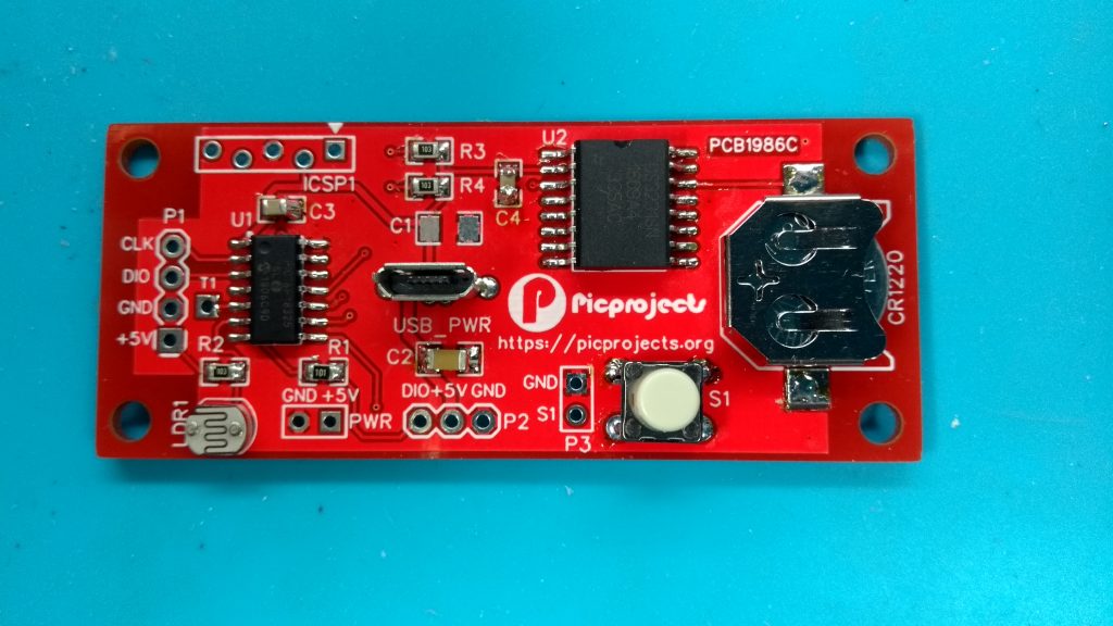
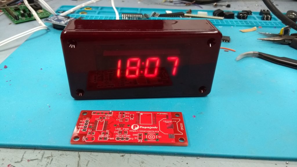
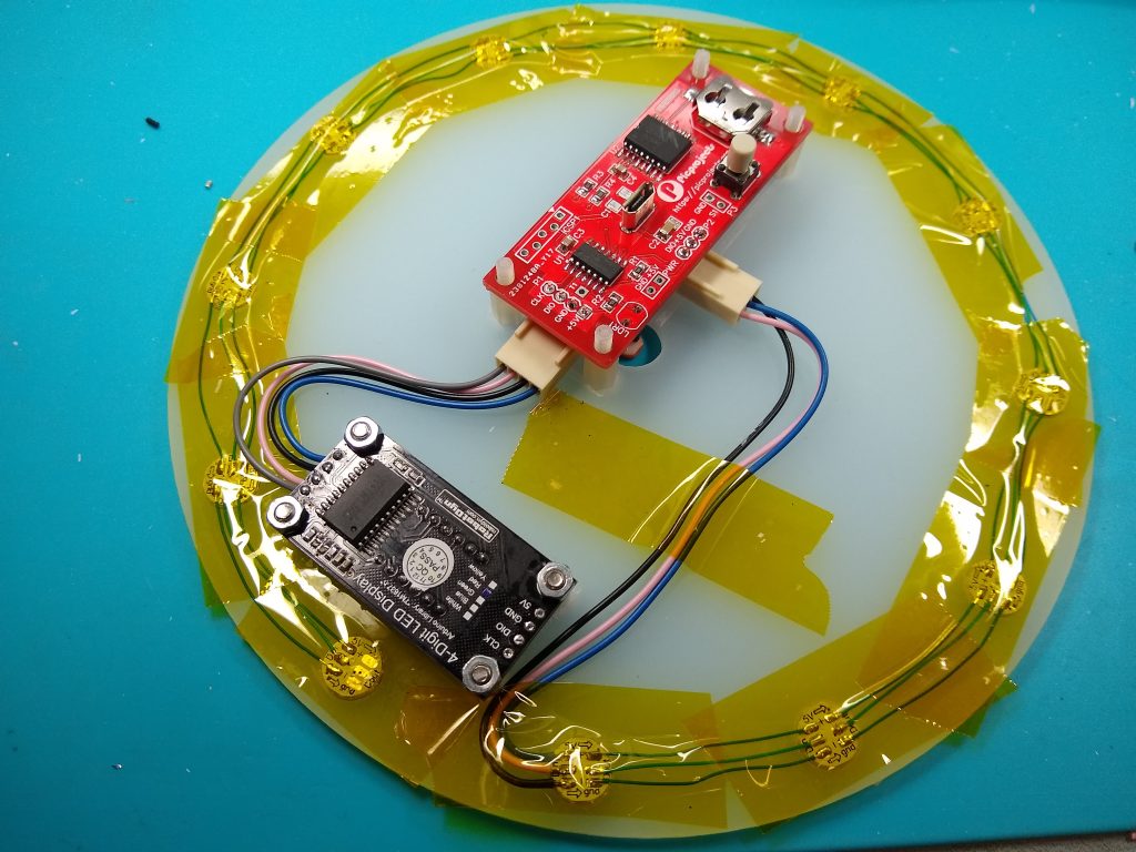
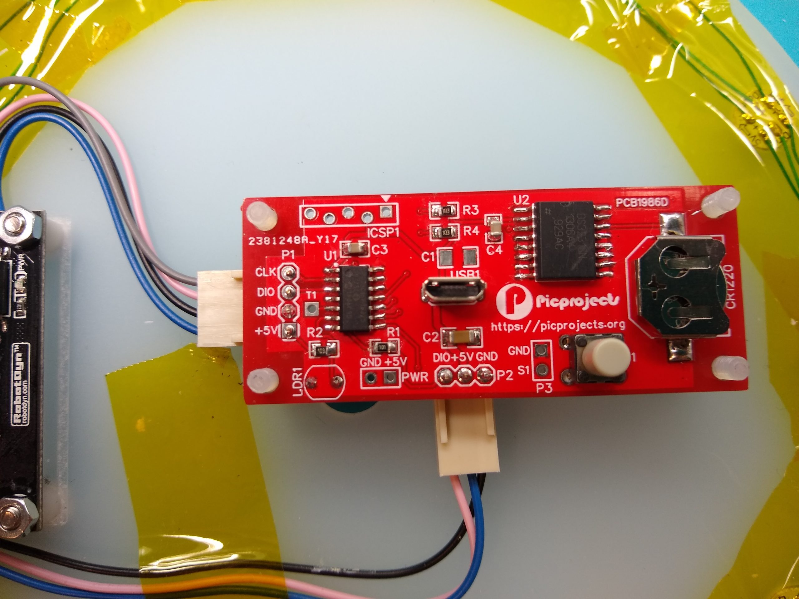
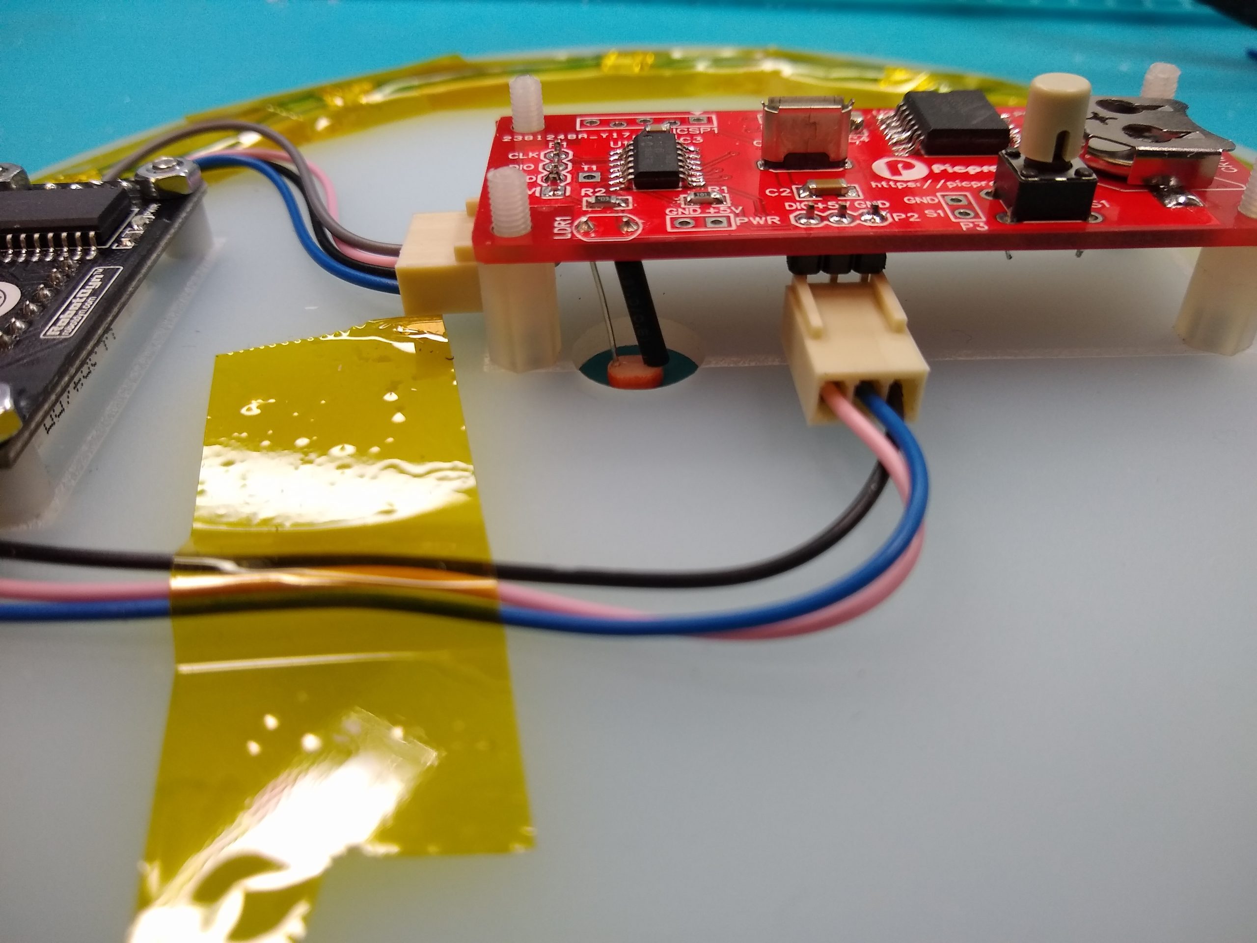
First problem I ran into was not having any PIC16F18325 microcontrollers in SOIC package. I checked my previous sources and no-stock until March/April 2022 so not a good start. At this point I could see how this might turn into another two years. Determined that I wasn’t leaving the workshop until it was finished I took a previous prototype PCB I had lying around and de-soldered the PIC for reuse. The control PCB was duly assembled, PIC programmed, battery installed and an initial test showed all was good.
The acrylic backplate and the vinyl record had been milled out on my CNC3018 router two years previously along with the smoked acrylic ‘windows‘ for the LEDs. A little reaming and counter sinking of the holes for the PCB mounting screws was all that was left to do here.
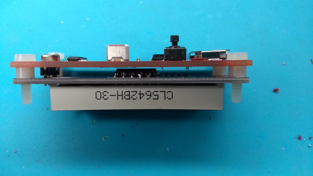
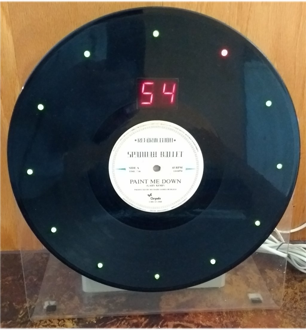
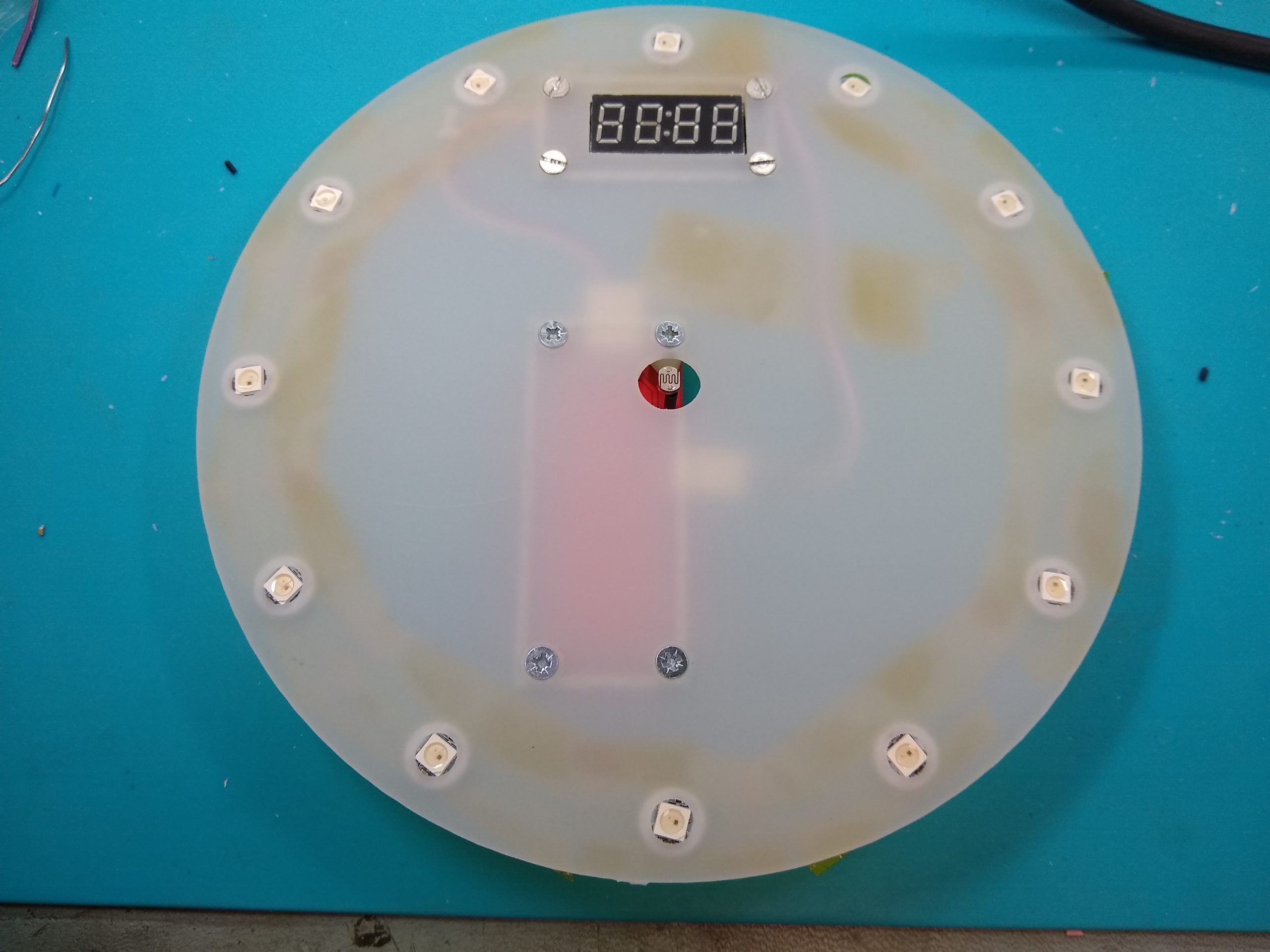
Next was the installation of the WS2812 RGB LED modules. I previously bought a large array of these pre-soldered onto small PCBs. I linked these together with Kynar wire then made up a short lead with 0.1″ Molex connector to the PCB. The LEDs and wiring were held in place using Kapton tape. I did this rather than gluing them in place to make it easier to fix any issues with the modules or wiring. As it turns out there weren’t any. The 7 segment display is a 0.37″ RobotDyn module using a TM1637 control IC.
To fix the 7″ single record to the acrylic backplate, I drilled a couple of 5mm holes in the backplate then positioned and aligned the record over the front and clamped it in place. The record is spaced off the back plate about 1mm, this allowed me to inject hot-melt glue through the 5mm holes which then stuck them together. It’s still possible to separate them if needed by sliding a knife inbetween the backplate and record; I know, I have done it 🙂

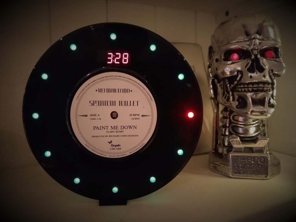
In retrospect I wish I had used some WS2812 LEDs in a 5mm round opaque package. This would have been true to the original and I hope diffuse the light better than the 5050 SMD parts. In fact I have aquired some and may yet build a redux V2 clock – maybe 😉
Original and Redux
It’s now 36 years since I made the original 12″ version of the clock. Ever since I started messing around with PIC microcontrollers it has been something I have always had in the back of my mind as a project I should do again. I’d kind of expected the original clock to die at some point and then I’d have a reason to do it, but amazingly its run 24/7 since 1986. Apart from a repair due to overzealous dusting breaking a wire to an LED, it just keeps going. It would be interesting to see if the PIC version lasts as long, not that I’ll be around to see that – 😨
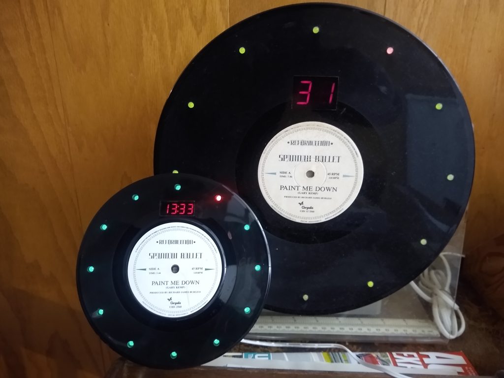
So the photo below shows the original and redux clocks together for comparison. The original only displays the minutes on the 7-segment LEDs, while the new version using the 4-digit display shows hours and minutes, or minutes and seconds as well as the option to display temperature. One thing the original does better is the dimming of the display. The TM1637 has brightness control but it is in discrete steps, so the new verison has three stepped levels of brightness while the original does a pleasing PWM fade.