In all the time I’ve been been messing around with PIC microcontrollers I’ve never done a simple 7-Segment LED clock, and it’s something I’ve always wanted to do.
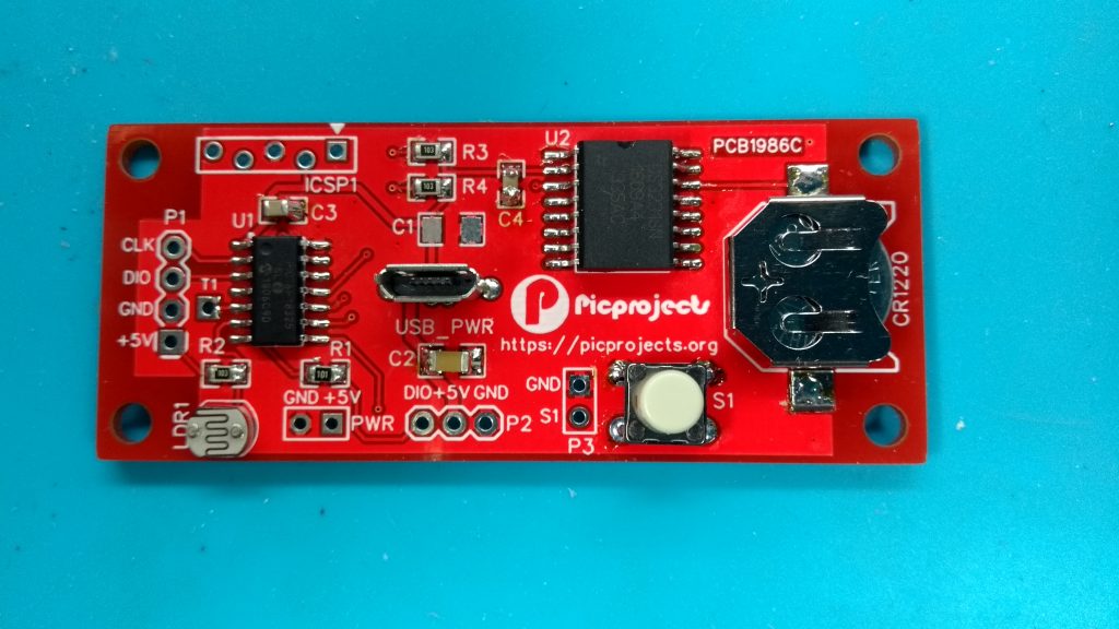
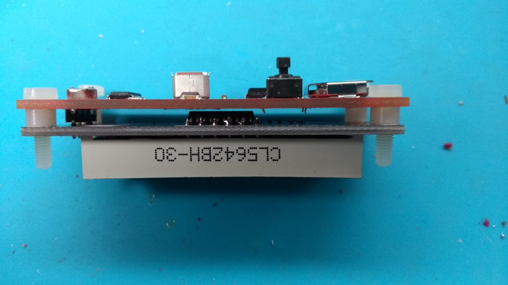
For the Record Time Redux project I’m currently working on I needed to design a control board for it. I started working on a PCB layout and then thought, why not make the board so it could also fit on the back of the 7-Segment LED module. So I came up with the board shown here, it fits to the back of the 0.56″ RobotDyn 4-digit clock module (see here) and turns it into a compact USB powered LED clock.
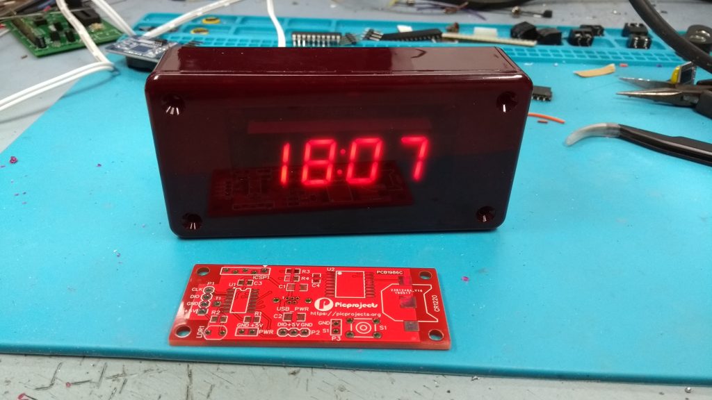
I fitted the assembled boards into a Hammond translucent red 1591 style case (size 100 x 50 x 21mm )
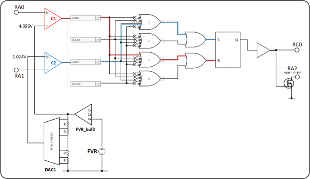
There is an often used phrase “You should have used a 555” where a microcontroller has been used to do something a 555 timer could have done. So this got me thinking, could you configure the PIC microcontrollers Core Independant Peripherals to behave like a 555 timer? Read on for the answer.
While this may seem pointless, and yes I know it is, it was just something that I kept thinking about so in the end I had to do it to satisfy my curiosity. Anyway it’s a practical exercise in using the Code Configurator tool in MPLABX.
I recently got hold of some 7-segment LED modules that use the TM1637 LED drive controller IC. You can find these on eBay, Amazon and all the usual resellers of maker hardware. Since I had some ‘fun and games’ getting them working, I thought I’d share my findings here.
I2C it is not
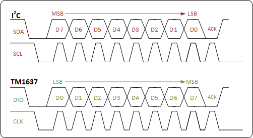
The first thing to catch me out was the I2C interface that isn’t. The translated data sheet for the device describes communication with the TM1637 by means of a two-wire bus interface. At first glance it looks like an I2C interface, however the datasheet points out that “it is not equal to I2C bus protocol totally because there is no slave address“. Well that’s not too much of a problem, it does mean you can’t have any other devices on the bus but that’s not a show stopper.
What it doesn’t make clear is that it expects data to be sent LSB first, and this caught me out for a while. Standard I2C sends data MSB-to-LSB. If you’re bit-banging the interface it’s easy enough to reverse the bit order of data being shifted out, but if you want to use the PIC’s MSSP module then it’s going to send it MSB first, so you need to reverse the byte before loading the SSPxSR buffer register.
Bit ordering
For example the TM1637 Data command setting for ‘Write data to display register with automatic address adding‘ is 0b01000000 (0x40) so you need to load the SSPxSR register with 0b00000010 (0x20) so it arrives at the TM1637 LSB first.
Capacitors on the CLK & DIO lines
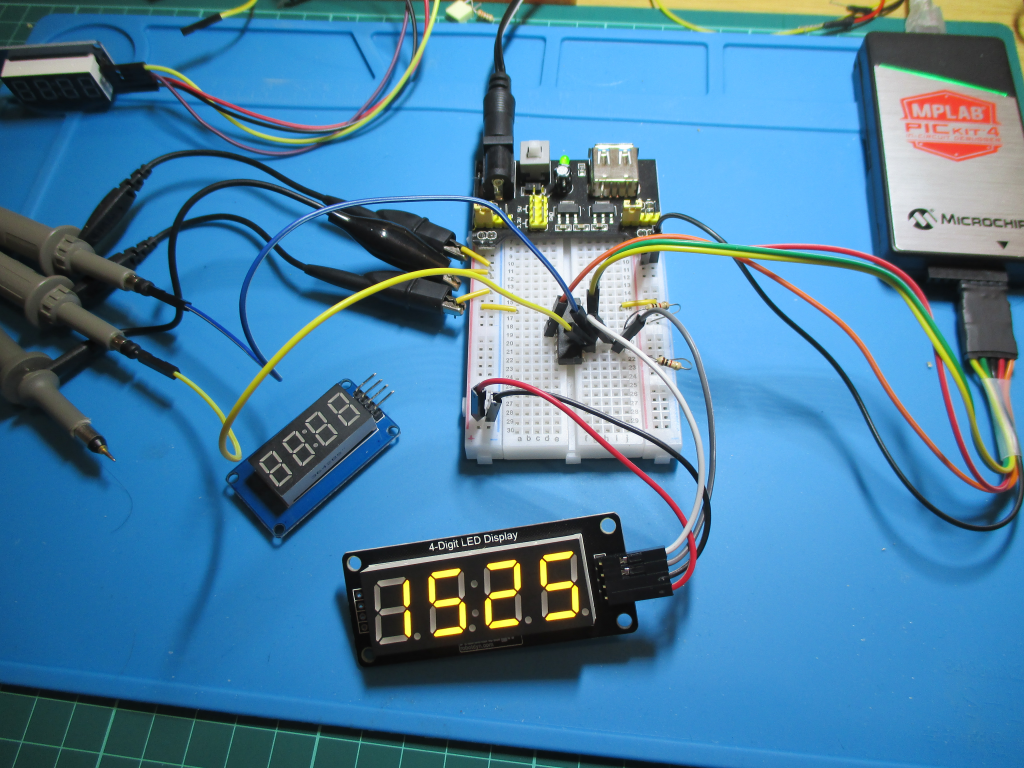
The next problem I had was not the TM1637 itself but one of the modules I’d bought. Whenever I’m developing stuff I like to hook up an oscilloscope to the hardware signals to see what’s happening. It can be a fast way to verify that things are doing what you expect, and it can save a lot of time troubleshooting when things aren’t working. In this case the control signals appeared to have large capacitive loading on them, at least the RobotDyn module did.
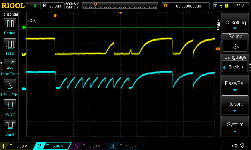
The I2C bus relies on pull-up resistors to pull the signals high, devices on the bus only drive it low. Instead of a nice sharp rising edge, what I was seeing was a perfect RC time-constant curve. I ended up adding 330ohm pull-up resistors to get it working at all, and at much reduced clock rate.
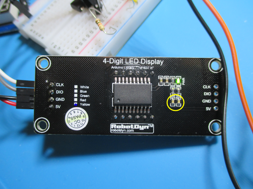
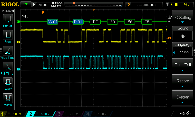
The datasheet for the TM1637 suggests using 100pF capacitors on the CLK and DIO lines, but what I was seeing was the effect of something much larger than that. In the end I found a schematic for the RobotDyn 4-digit LED Display I was using and it showed 10nF capacitors on the CLK and DIO lines. I decided to remove the capacitors completely and the display now works fine with a 400KHz I2C clock and the original 10K pull-up resistors fitted to the board.
In the pictures below I’ve highlighted the capacitors that need removing and the before and after signals on the oscilloscope.
10nF capacitors circled
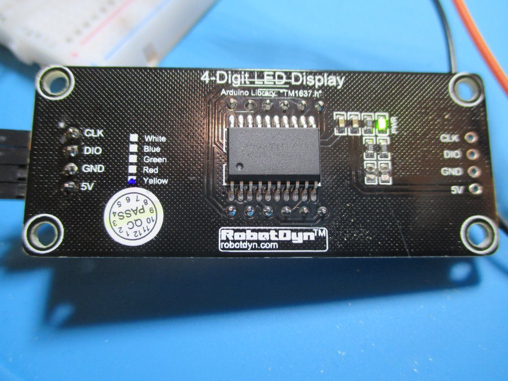
with capacitors removed
Test circuit, now working
With 10nF capacitors on CLK & DIO lines
After capacitors removed
Centre Colon
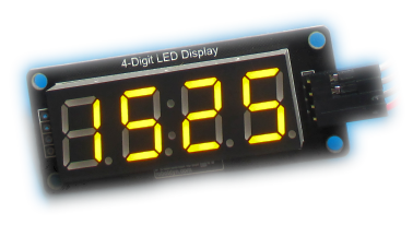
The modules I bought are 4 digit clock style LED displays with the centre colon. The decimal points on each digit aren’t conneced, however the centre colon is connected to the SEGment8 output of digit 2 (Display address C1H in the datasheet). I guess this wiring is specific to the modules I bought, but both the RobotDyn module and a couple of no-name modules had the colon connected the same way.
The code I wrote for testing can be download below, it’s the packaged MPLAB X project, with source code.