
There is an often used phrase “You should have used a 555” where a microcontroller has been used to do something a 555 timer could have done. So this got me thinking, could you configure the PIC microcontrollers Core Independant Peripherals to behave like a 555 timer? Read on for the answer.
While this may seem pointless, and yes I know it is, it was just something that I kept thinking about so in the end I had to do it to satisfy my curiosity. Anyway it’s a practical exercise in using the Code Configurator tool in MPLABX.
The PIC16F18345 has two comparators, a CLC module that can be configured as an SR latch and outputs that can be configured as Open Drain. So in theory these are all the building blocks we’d need to make the PIC operate like a 555 timer IC. There are some limitations obviously; the supply voltage range is limited and the three 5K resistors that make the voltage reference for the comparators aren’t present. However there is a Fixed Voltage Reference module (FVR) and a Digital-to-Analogue Convertor (DAC1). While these won’t give the same 1/3 & 2/3 VDD reference voltages of the 5K resistors in a 555 timer, they will give two fixed voltages that can be used by the comparators to the same end.

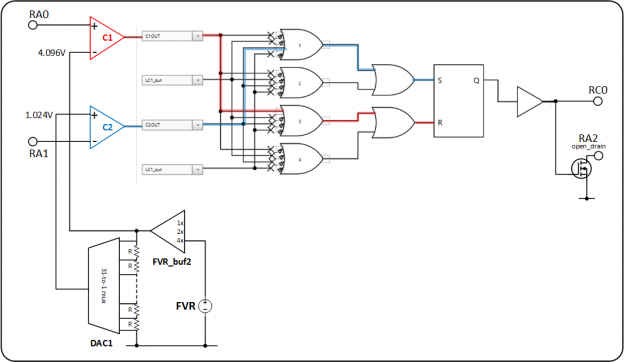
Using MPLAB Code Configurator I set up the PIC as shown in the diagram to the right. The FVR is used to provide a 4.096V reference to Comparator 1 and also DAC1. The DAC is then set to output 1.024V and provides the reference voltage for Comparator 2. The comparator outputs then connect to CLC1 configured as an SR latch. The
Peripheral Pin Select (PPS) feature allows the output of CLC1 to connect to two I/O pins, RC0 is configured as a normal push-pull output and RA2 is configured in open-drain mode to emulate the discharge pin on a 555 timer.
Does it work?
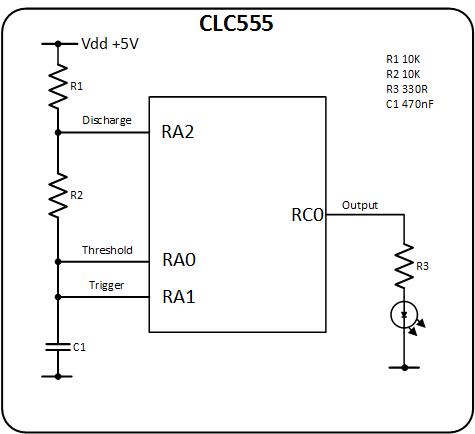
Once the code was uploaded to the PIC I connected it up in a classic astable multivibrator configuration as shown in the schematic to the right. Since RA0/RA1 are also used for the ICSP programming, the circuit has to be disconnected before programming the PIC, then reconnected afterwards.
The connections are labeled with the equivalent pin names used on a 555 timer for comparision. Below is the circuit running on a breadboard. The three probes are connected to the oscilloscope and the output can be seen in the screen captures further down the page. As well as 470nF capacitor I tried it with a 100uF and 100nF capacitors and also 1K resistors and it behaved as expected.
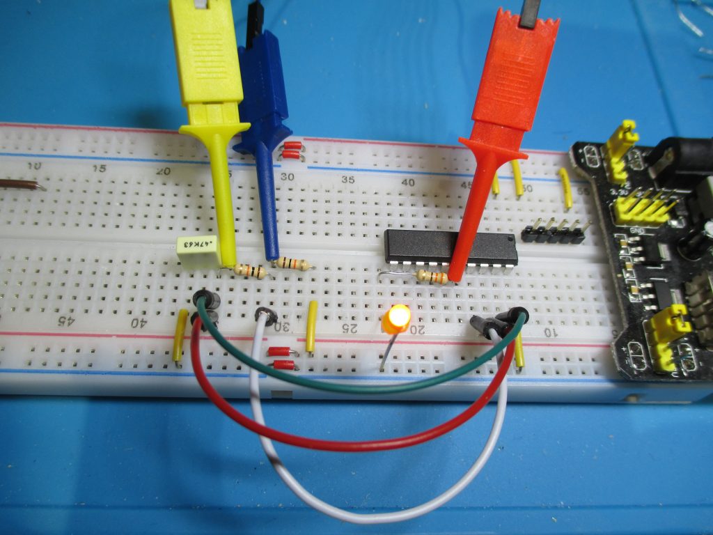
470nF timing capacitor 
100uF timing capacitor 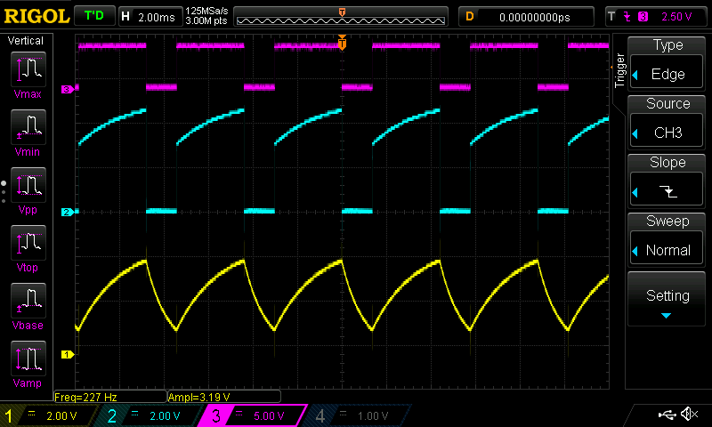
100nF timing capacitor
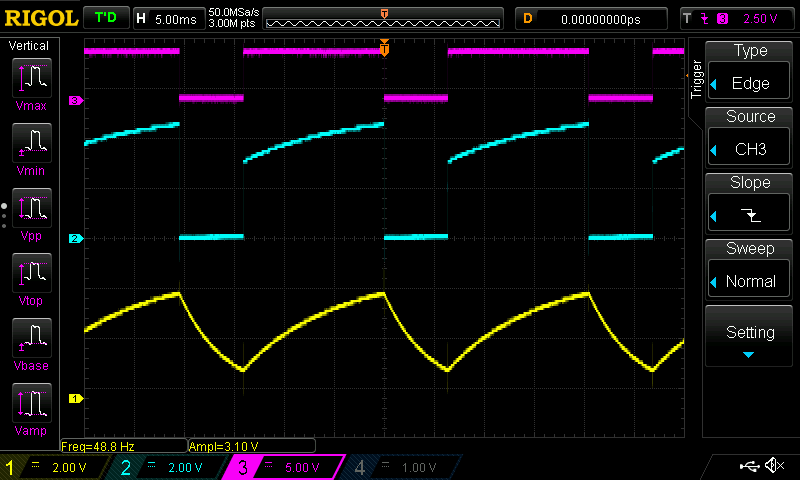
Connections / ‘scope traces are:
- Yellow – Trigger/Threshold (RA0/RA1)
- Blue – Discharge (RA2)
- Red – Output (RC0)
The code
All the work is done by the Core Independant Peripherals, the C code just initialises the device and then does nothing as you can see below.
#include "mcc_generated_files/mcc.h"

/*
                         Main application
 */
void main(void)
{
    // initialize the device
    SYSTEM_Initialize();


    while (1)
    {
        // Add your application code
    }
}
The MPLABX project files can be downloaded here.