
I’ve been working on the Record Time Redux clock project for a while and needed a PCB designing for the control circuit. When I came to do the PCB layout I looked at the 50x19mm RobotDyn 7-Segment LED modules I had lying around and thought why not design a dual purpose PCB. The board could be used for the original project, but would also piggy back onto the LED module to make a classic 7-segment LED clock. The clock functionality was already written into the code for the original project so needed very little modification to run as a simple LED clock.
So that’s what I did – read more below…
Description
The clock has the following features:
- Time in 12 or 24 hour format
- Toggle display between HH:MM or MM:SS
- Display temperature at four selectable intervals
- Temperature in Celsius or Fahrenheit
- Manual or Auto-brightness control
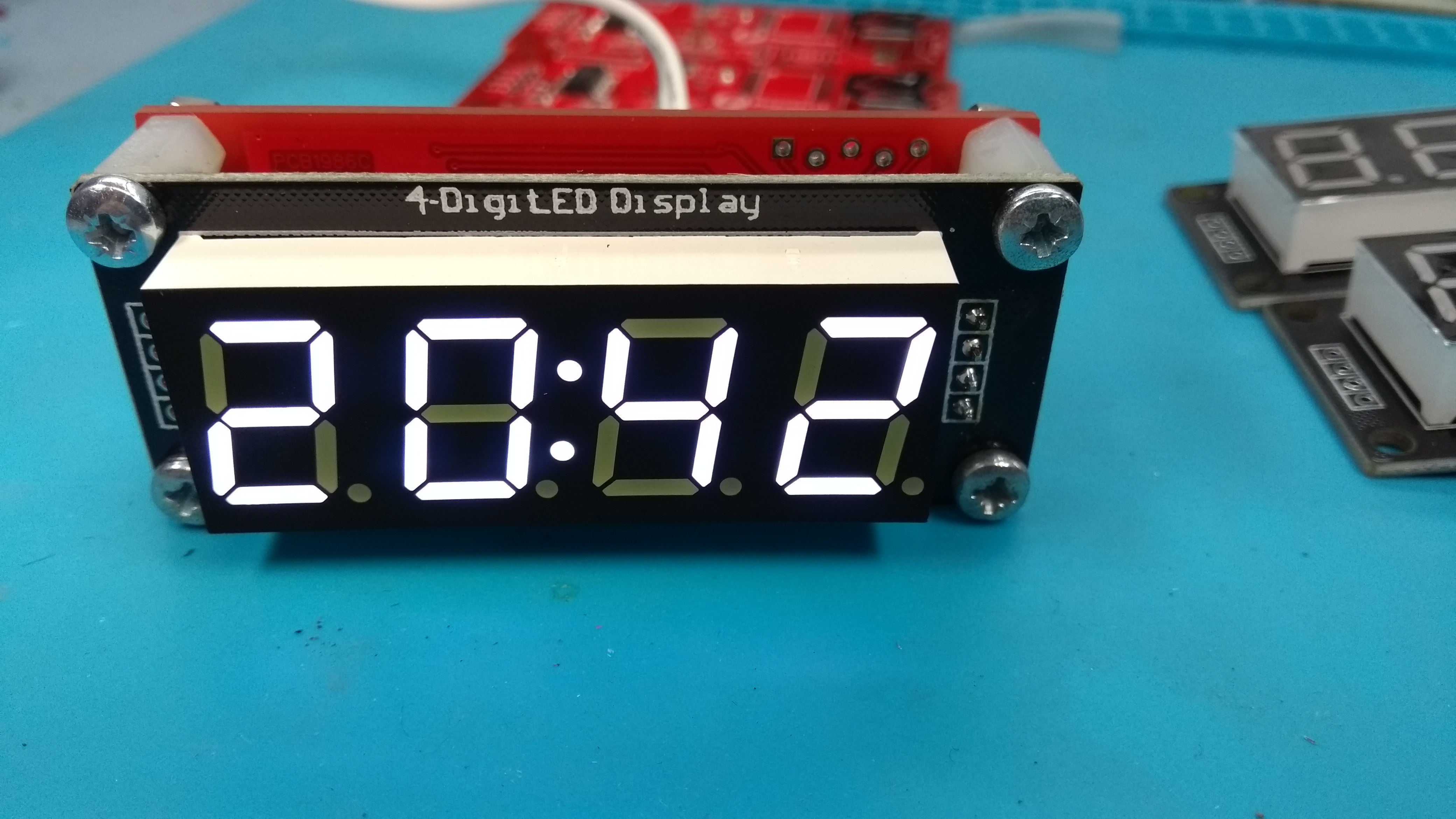
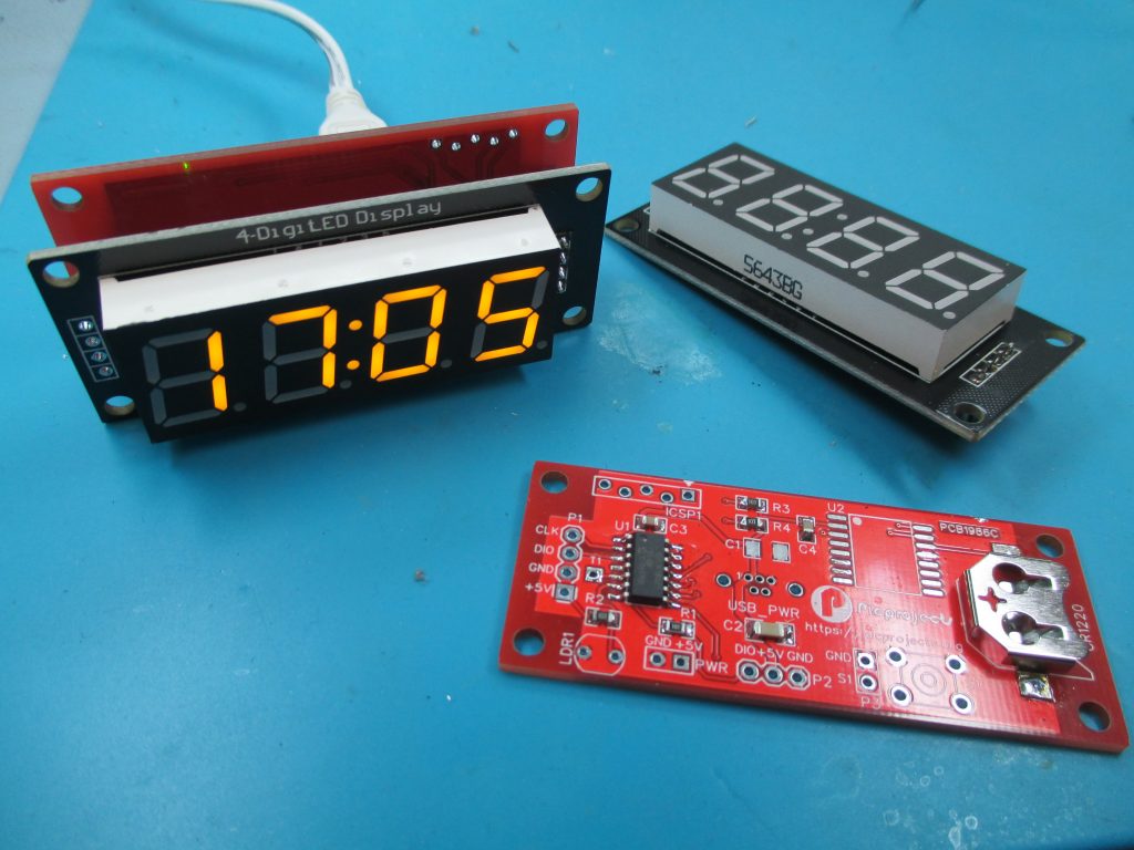
The PCB has the same dimensions as the RobotDyn 4-Digit LED Display Tube, 7-segments, TM1637, 50x19mm module. The genuine part can be found on various maker sites on the Internet including eBay. They’re targetted at Arduinio users and of course there are lots of clone versions around too.
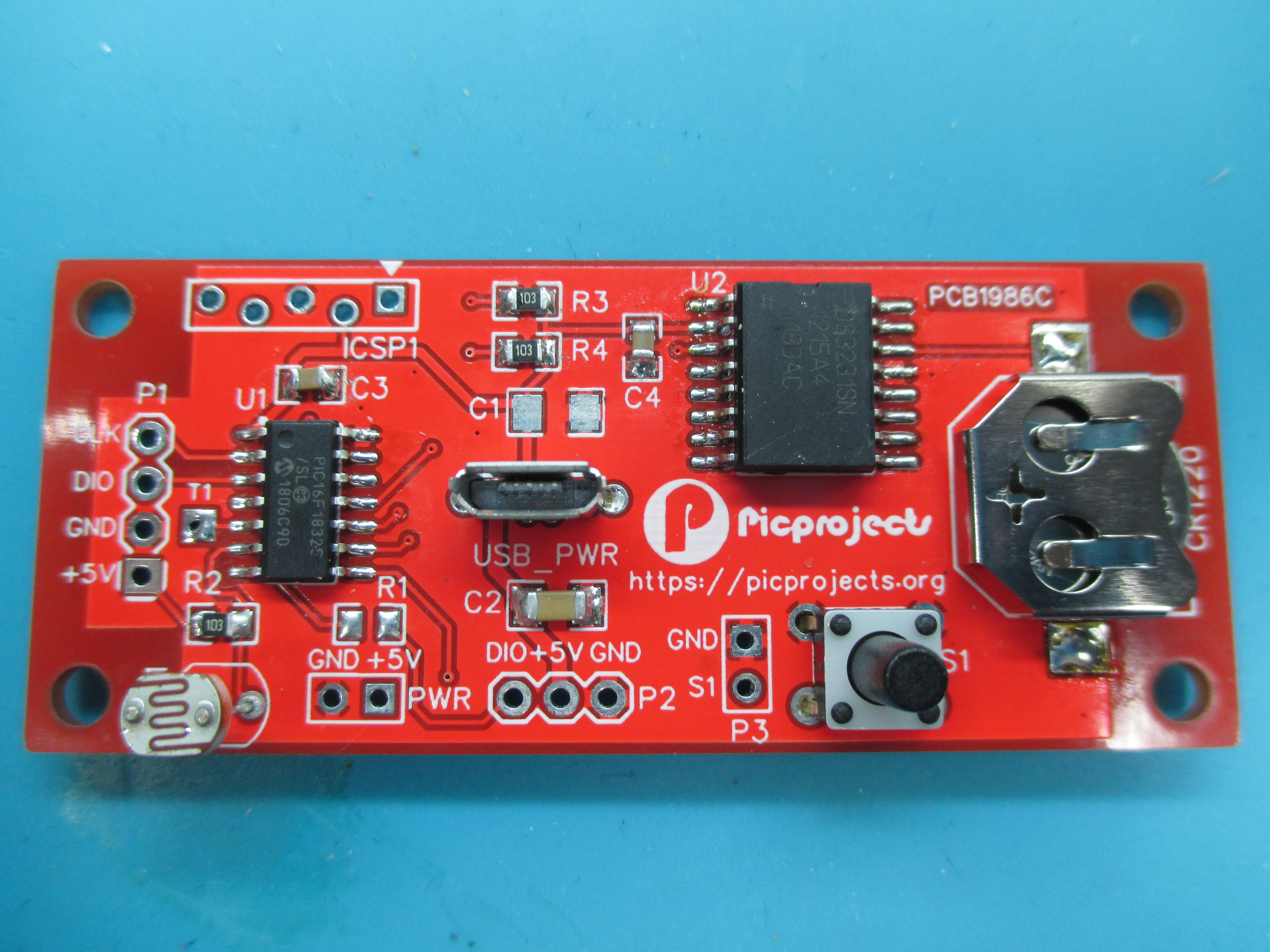
The circuit uses a PIC16F18325 microcontroller and DS3231 Real-Time-Clock IC for time keeping. The TM1637 LED module interfaces to the board through a 4-pin header mounted on the reverse of the PCB. A CR1220 lithium coin cell battery provides backup power to the RTC.
The circuit requires a 5 volt power supply. There is a Micro-USB socket to allow it to be powered from a USB port or power supply. There is also a 2-way header ‘PWR‘ for power on the edge of the board if you don’t want to use the USB connector.
The clock will operate from a 3.3 volt power supply, although this will may result in a dimmer LED display.
Setting and adjusting of the time and options is done using a single switch. There is a tactile switch mounted on the PCB for this, also another 2-way header if you want to mount a switch off-board.
The clock allows the LED display to be set to one of 3 brightness levels. These can be manually set, or an LDR on the board allows an auto-brightness mode to be used. If you don’t fit the LDR you can still manually set the display brightness, but auto-brightness won’t do anything (it will just be dim)
TM1637 LED module
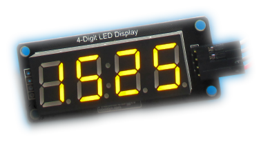
The LED module is based on a TM1637 driver chip. The LED modules are available with clock style centre-colon or decimal point LEDs. They also come in two sizes;
– 50x19mm (0.56″)
– 30x14mm (0.36″) .
For this project you need the 50x19mm LED module with clock-style centre colon.

For some reason all these LED modules seem to have two 10nF capacitors connected to the CLK and DIO signals. These are far too large and distort the I2C signal from the control board to the extent it won’t work. Therefore you must remove these capacitors when used with this project. See the image and for more infomation on this see here.
You might also want to remove the PWR LED, it doesn’t make any difference to the clock functionality but you may not want a green LED glowing in the background.
I’ve bought quite a few of these modules with various coloured LEDs. Some of the clone displays I’ve tried seem rather dim in comparison to others. For this reason I would suggest trying to get hold of a genuine RobotDyn module, or at least buy a couple or displays from different sellers.
Finally, check the order of the CLK, DIO, GND and 5V signals on the 4-way connector. I have some 0.36″ versions of this module where the GND and 5V signals are reversed which will ruin your day if you connect it directly to the control board.
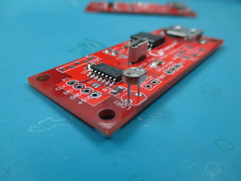
Control PCB
The PCB design is on the EasyEDA website and you can order 5 PCBs for $2 through JLC PCB direct from the site (at the time of writing).
Schematic
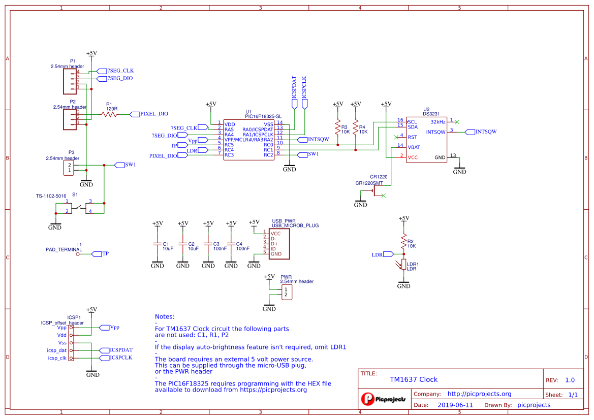
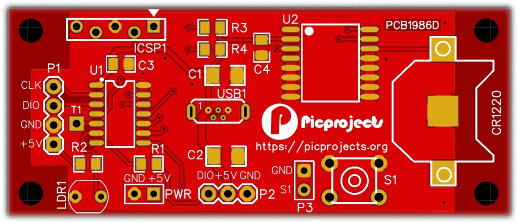
Component notes:
- Resistors are all 0805 size
- Capacitors are multi-layer ceramic X5R or X7R
- Capacitors C3, C4 100nF, 0805 size, C2 is 10uF/10V, 1206 size
- R1 and C2 are not used so no need to install them.
- The CR1220 battery holder is surface mount part, like RS Components part 219-7926
- Use a 3 volt CR1220 lithum coin cell
- S1 is a thru-hole 6mm tactile switch, choose a button length to suit you application
- USB-PWR connector is a vertical micro-USB type-B connector, like RS Stock No.122-5097
- U1 is a PIC16F18325 SOIC and will need programming (see Firmware section)
- U2 is a DS3231(S/SN/M). The S, SN and M parts will all work.
Operating temperature range:
DS3231S ( 0oC to +70oC )
DS3231SN (-40oC to +85oC )
DS3231M (-45oC to +85oC )
The M part uses a MEMS resonator with ±5ppm accuracy, the S/SN parts use a TCXO Crystal with ±2.0ppm accuracy from 0oC to +40oC and ±3.5ppm from -40oC to +85oC
For more information see the data sheets DS3231S/SN, DS3231M
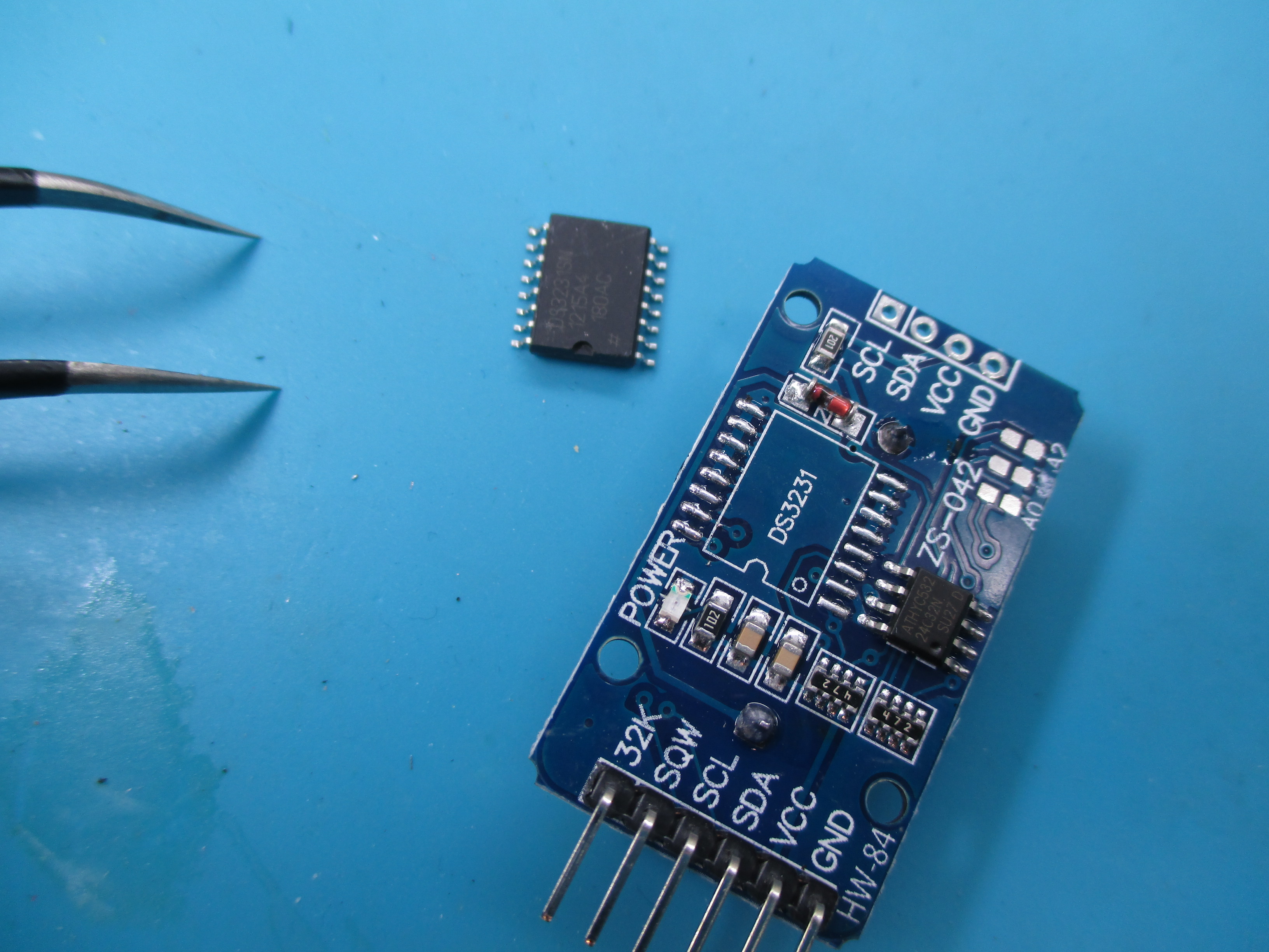
The DS3231 RTC chip is quite expensive to buy from distributors, however you will find this chip on RTC clock modules sold on eBay and they are relativley cheap. I buy the cheap module, desolder the DS3231 from the board and then reuse it.
Assembly
Before you solder the CR1220 battery holder to the PCB, tin the large pad on the PCB in the centre of the battery holder area with a thin layer of solder. If you don’t do this the red solder mask, although very thin, holds the battery a fraction of a millimetre away from the pad so it doesn’t make contact.
For the interconnect between the two modules I used a 4-pin 0.1″ (2.54mm) header on the LED module and matching socket on the control board. Four 10mm nylon spacers hold the boards together.


Firmware
The firmware is written in C using the free version of Microchip XC8 compiler. ( v2.05 / C99 )
The programmer ready HEX file and Microchip MPLAB-X project files can be downloaded below:
Hex file:
MPLAB-X Project:
Programming:
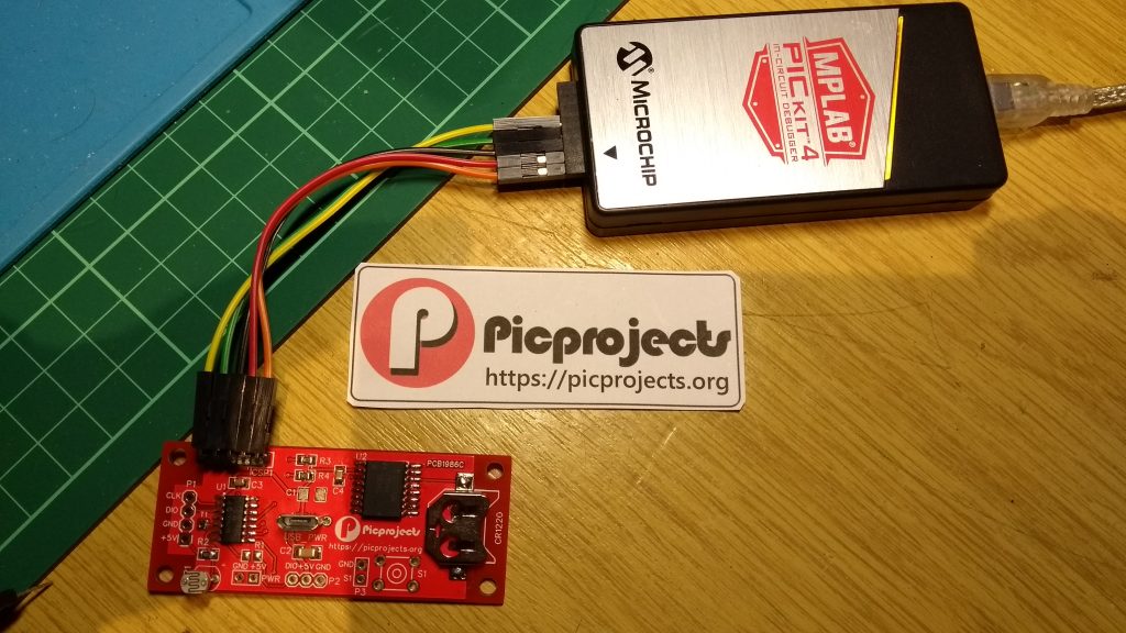
The PIC16F18325 is supported by the Microchip PICkit3 and PICkit4 programmers.
When programming, set the programmer to supply Vdd to the target, and don’t connect an external power supply to the board. It can be programmed with or without the LED module attached.
The PCB has an ICSP connector with offset holes to allow a 5-pin ICSP header to be ‘jammed’ into the board without having to solder it in place. This allows the PIC micrcontroller to be (re)programmed on the board after assembly.
Operation
A single switch is used to set and adjust the time and clock options.
During normal clock time display, a short press of the switch toggles between display of HH:MM and MM:SS
To adjust the time and display options, press and hold the switch until it shows [-CL ]
When in the Adjust menu, the switch functions as follows:
– press and hold sets/selects the displayed option and moves to the next adjustment.
– repeated short press cycles through current adjustment values.
Adjust select
- Adjust select
[-CL ] Adjust Time
[-OPt] Adjust Options
[-End] Exit without making changes
Adjust time [-CL ]
- [12: ] or [12: P] set hours
hours format depends on clock time display format set in options
00 – 23
1 – 12 A / 1 – 12 P
– - [ :00] set minutes
:00 – :59
– - [ 00] set seconds
00 – 59
– - save time and exit back to clock display
Adjust options [-OPt]
- [12h ] set clock time display format
[12h] – 12 hour format
[24h] – 24 hour format
– - [t 0 ] set display temperature.
[t 0 ] – temperature display off
[t 1 ] – 4 seconds every 10 seconds
[t 2 ] – 10 seconds each minute
[t 3 ] – 10 seconds every two minutes
– - [t oC] set temperature display format
[t oC] – Celsius
[t oF] – Fahrenheit
– - [br A] set display brightness
[br A] – auto-brightness (set by light level on LDR)
[br 1] – dim
[br 2] – mid
[br 3] – bright
– - save options and exit back to clock display
Each time the clock is switched on it reads the saved options from non-volatile memory. At this time it checks the saved options, if they are okay the display will briefly show [Good].
If it detects invalid saved options it will show either [Err1] or [Err2]. It will then attempt to save default options. You will see [Err1] when you first power on after programming the microcontroller, thereafter you shouldn’t see an error unless there is a fault with the nv memory.
When the temperature display format is in Fahrenheit, it can only display up to 127 oF. If the temperature goes above this it will display [hhho]
The temperature is obtained from the RTC chip and this only updates every 64 seconds. Therefore even if the display is set to show temperature more frequently it will only update the actual temperature every 64 seconds.
According to the DS3231 datasheet, temperature accuracy is +/- 3oC I’d expect the accuracy is generally better than that, but just be aware of what the specifications says.
.
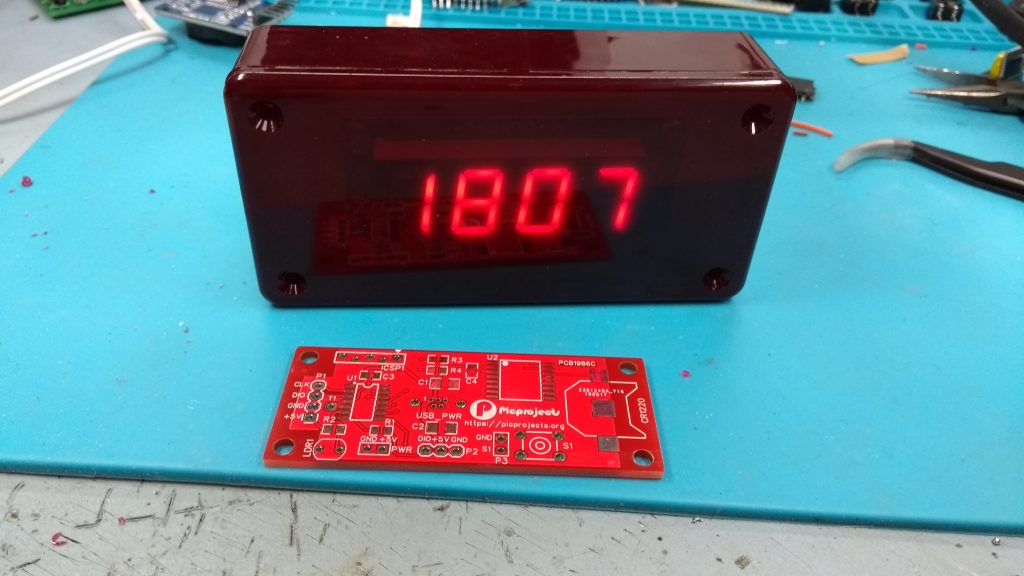
The image above shows the assembled boards fitted into a Hammond translucent red 1591 style case (size 100 x 50 x 21mm )