
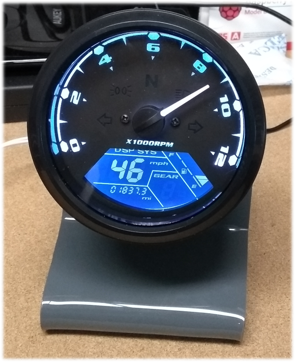
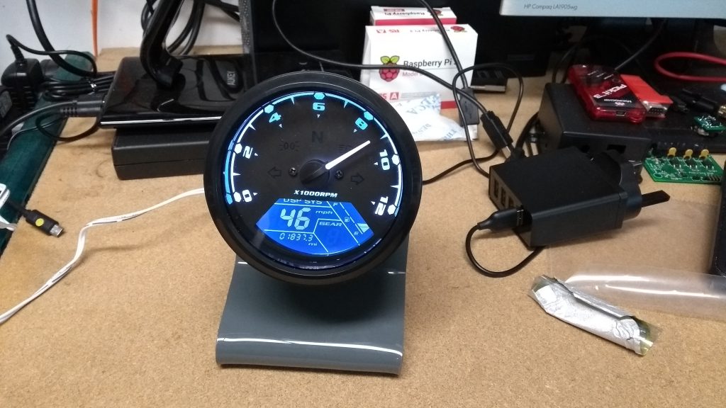
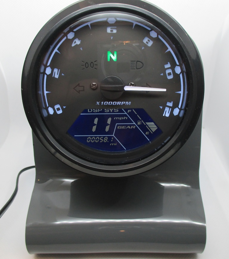
This project uses an electronic instrument cluster like that shown on the right as a novelty clock. These units can be found on eBay, usually described something like “Universal Motorcycle LCD Digital Speedometer Odometer Motorbike Tachometer Gauge“, and selling for around £20.00.
The idea for this came from a post on the Hackaday website where they had done something similar using an Arduino. The hours are displayed on the analogue RPM section and the minutes as speed on the digital LCD.
- The Instrument Cluster
- Differences between instrument clusters
- Control Board
- Construction notes
- Connector and Cable Harness
- Firmware
- Programming and Testing
- Tuning Speed Data
- Operation
The Instrument Cluster
Before we get to the project in detail I want to cover the instrument cluster modules to manage your expectations for this project. You need to know that they may all look the same but they are not, and some just won’t work well with this project.
After I received the first instrument cluster I wrote some simple code to drive the tachometer and speed inputs. The tachometer was accurate, the speedometer, as you might expect, overread by about 5%. I put an error correction into the speed signal, but despite this I could not get the speedometer to read consistently for all speeds between 1 and 59MPH. I tried setting the instrument to different tyre circumferences and pulses-per-wheel revolution. Whatever I tried it just wouldn’t read correctly across all speeds, and since speed would correspond to minutes, this wasn’t going to work for a clock. In the end I bought a second unit from a different seller on eBay.
One of the differences between the first and second units I bought is that the second one allows the tyre circumference and pulse-per-wheel revoltion to be set higher. By setting the tyre circumference to 2.8M and the pulses-per-wheel revolution to 12 it works well. This seems to be the key to getting it to work reliably, since even the new unit wasn’t very good when set to a smaller tyre and fewer pulses per wheel revolution. I subsequently bought a third unit, which appears the same as the second one and importantly, supports the same 2.8M wheel and 12 pulses/wheel revolution as the second unit. This third unit also works well so while my sample size is a bit small, it’s probably the answer to getting reliable display of minutes.
I’ll summarise the differences below, but the take away from this is that they may look the same on the eBay listing, but they may not be the same. I’ve also seen eBay listings that have several photographs of the unit and they show the two versions in the same listing. Therefore I’d suggest buying from a local seller to your region who accepts returns.
Differences between instrument cluster units
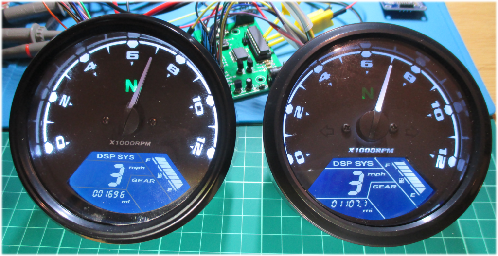
The two units, side by side. The one on the left is the original that doesn’t display minutes on the Speedometer reliably. The one on the right is the second unit that worked well. Listed below are some of the differences.
The fonts used for the text in the word “GEAR” on the LCD display and “X1000RPM” on the tacho are different, you can see this in the comparison photo above.
| Unreliable | Reliable |
| Lines demarking the LCD display sections are not illuminated | Lines demarking the LCD display sections are illuminated |
| “X1000RPM ” text on the tacho is not illuminated | “X1000RPM ” text on the tacho is illuminated |
| Low battery warning doesn’t work | Low battery warning works |
| Enter setup by pressing and holding the button on the rear while the unit is powered on, then enter id 888 | Enter setup by holding the button on the rear, then powering the unit up |
| Maximum tyre circumferece is 2.5M Maximum pulses-per-revolution is 9 | Maximum tyre circumferece is 2.8M Maximum pulses-per-revolution is 12 |
| Odometer does not display 10ths | Odometer displays 10ths |
The units are supplied with a wiring harness that has a 20-pin connector on one end and four connectors on the other. The 20-pin connector at the rear of the two units are wired differently. The four connectors at the other end were wired the same so you will need to trace the cables to identify the connections at the back of the instrument.
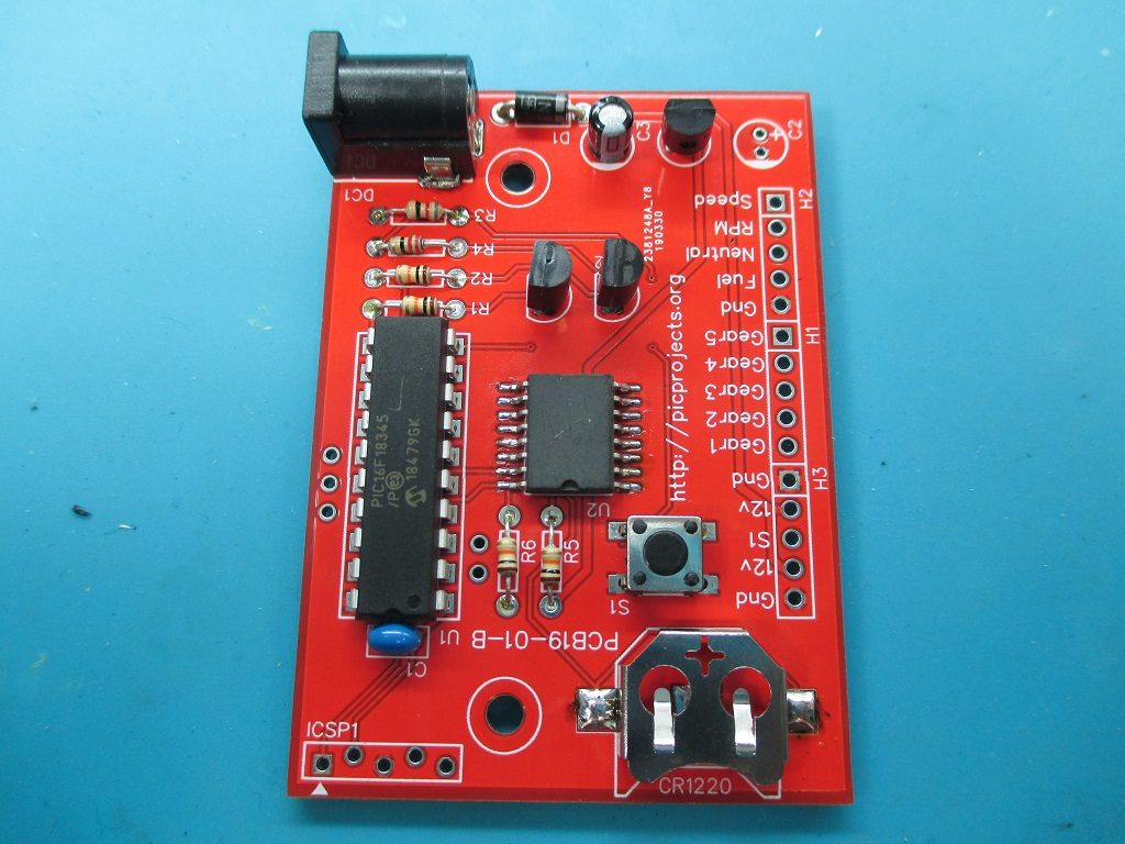
The Control Board

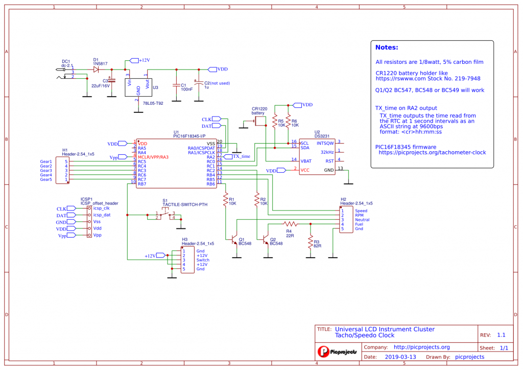
The Schematic and PCB layout can be found on the EasyEDA website
https://easyeda.com/picprojects/rpmclock
From the EasyEDA website you can generate gerbers, or order PCB’s online from JLC PCB. Open the PCB layout in the editor and click on the ![]() icon in the toolbar.
icon in the toolbar.
Construction notes
The circuit is very simple so shouldn’t be too difficult to build. There are a few things to be aware of which I cover below.
Diode D1 is a reverse polarity protection diode, you can use a 1N4001 here, but you may find that when operated from a 12 volt supply the low battery warning will come on. The 1N5817 Schottky diode has a lower forward voltage drop which may be enough to keep the low battery warning off, if not you’ll need to find a PSU with a slightly higher output like 13.8 volts ( but don’t exceed 15 volts)
The units I tested with seemed to draw around 110mA, if you go with a regulated DC PSU that can deliver at least 250mA that would be a good margin.
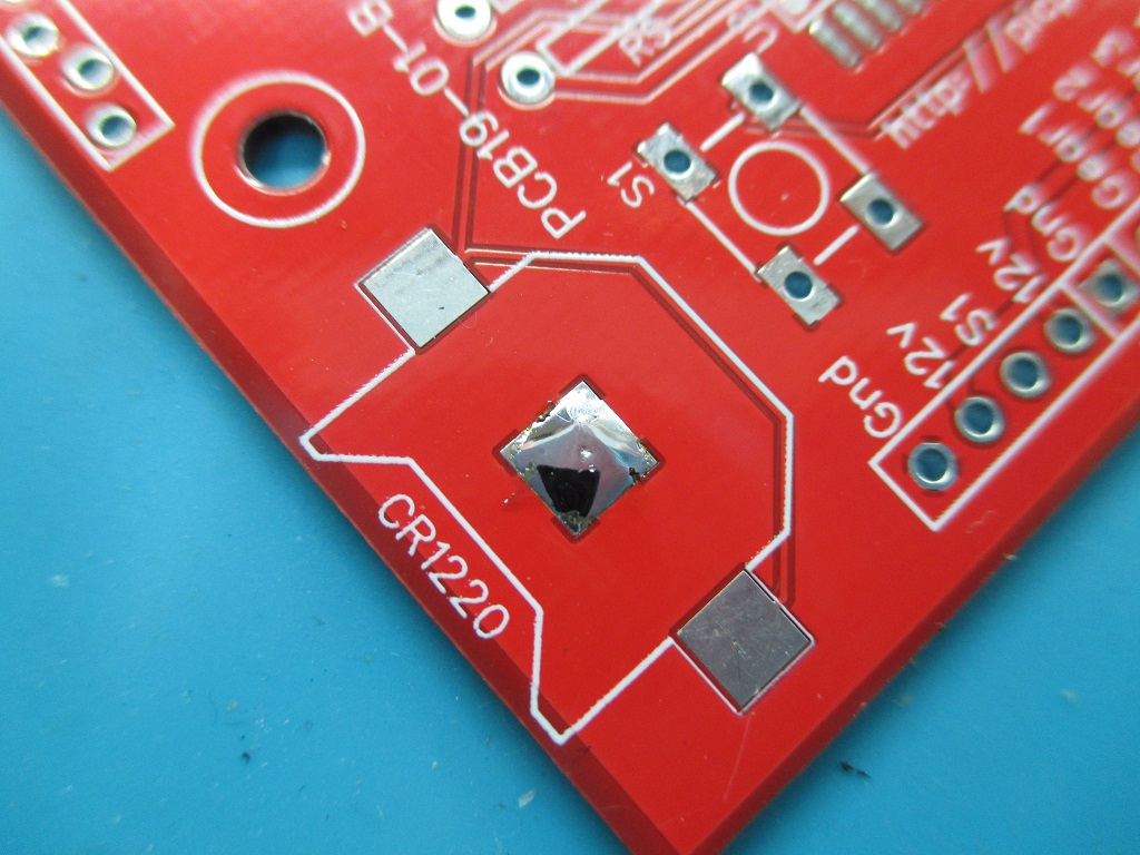
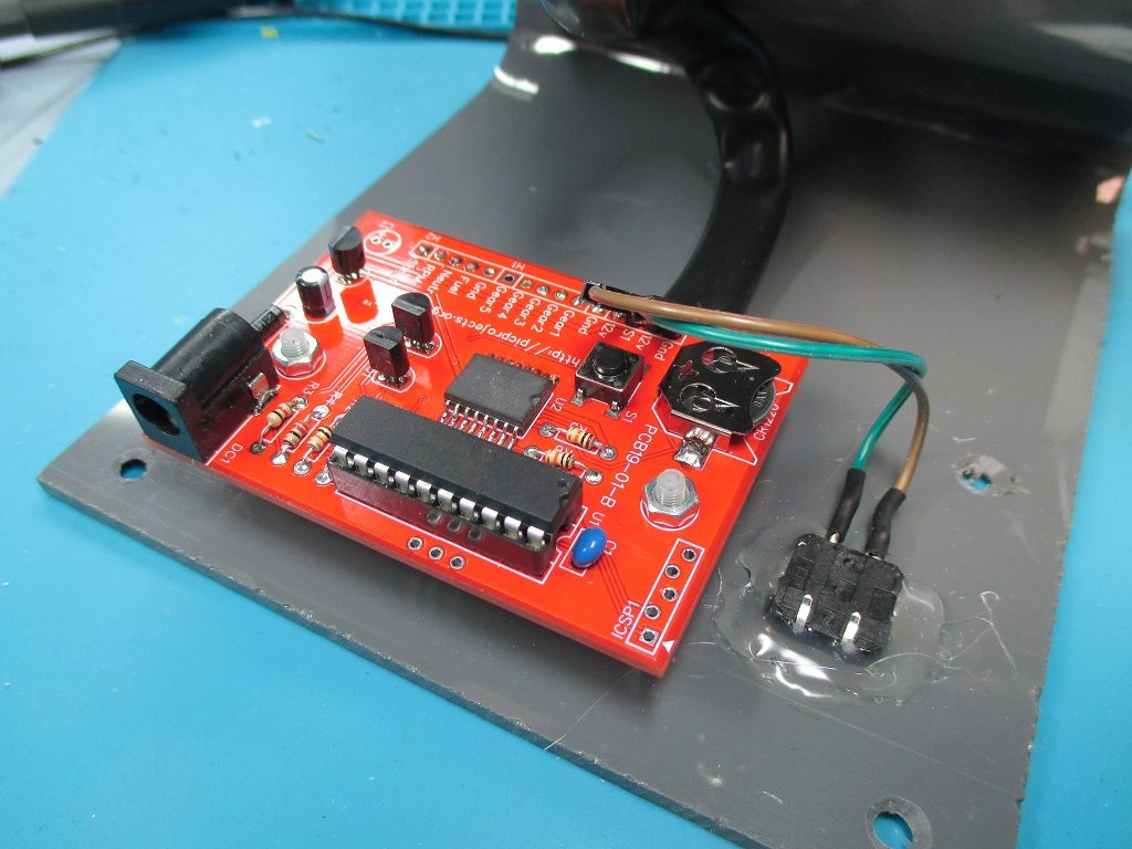
The CR1220 battery holder is a surface mount part and the -ve battery connection is a pad on the PCB. The solder mask is slightly higher than the pad on the PCB so you must tin the pad with solder, otherwise the battery won’t make contact. You can check if the battery is connecting to the ground pad by measuring the voltage between the Gnd pad on the H3 connector and the metal battery holder assembly with the battery installed. If it doesn’t measure about 3 volts ( assuming you have new battery installed! ), it’s not grounded.
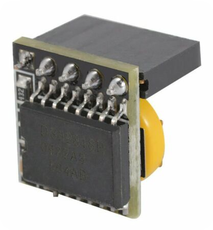
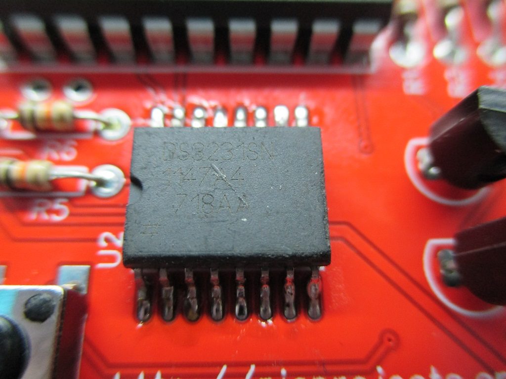
The DS3231 RTC IC are quite expensive to buy from distributors. I bought some cheap modules from eBay and desoldered the DS3231 from the board. While I was a little dubious about the origin of the parts, over the last two years I’ve run these in four clock projects and their accuracy over a 6 month period (the clocks get reset for daylight savings twice a year) has been within seconds. If you use a desoldered part, the pins may carry excess solder or get slightly deformed. When you resolder it to the control PCB make sure that all the pins actually connect. From experience, you think you have soldered a pin, but in fact it isn’t touching the pad on the PCB.
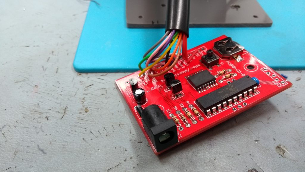
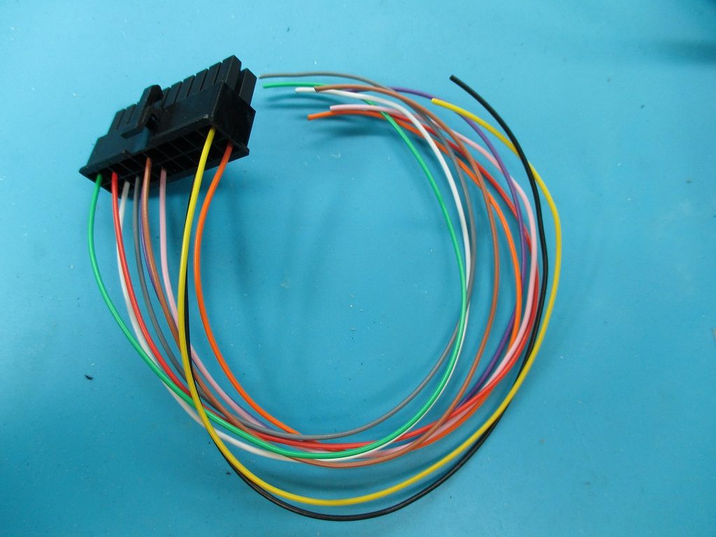
I didn’t use the wiring harness that came with the Instrument cluster, instead I made my own harness using thinner wire and only to the connections supported on the control board. The connector is a 39-01-2200 – Molex Female Connector Housing – Mini-Fit Jr, 4.2mm Pitch, 20 Way, 2 Row (Available from RS Components) and the crimp terminals are 39-00-0081 Molex MINI-FIT Male Crimp Terminal Contact 16AWG. You can also find these on eBay.
For the final version I soldered the PIC16F18345 directly onto the PCB without a socket. There is an ICSP connection on the board should you need to reprogram it. The ICSP header has off-set holes which allow you to ‘jam’ a 5-pin header onto the board and make good electrical connections without soldering. This works well for a one-off reprogram of the PIC, but if you plan on developing the code further yourself you’ll want to solder a header in there.
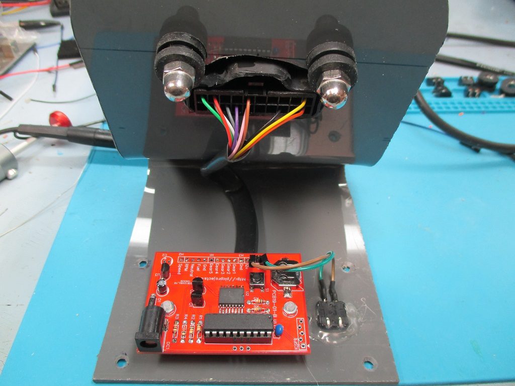
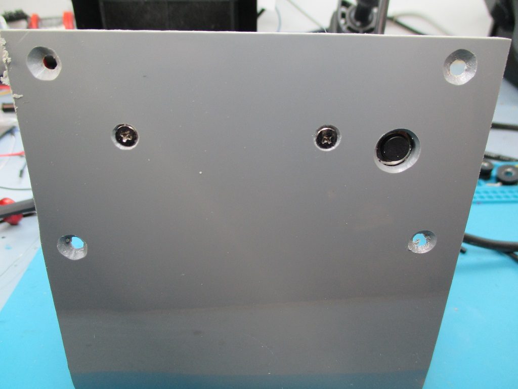
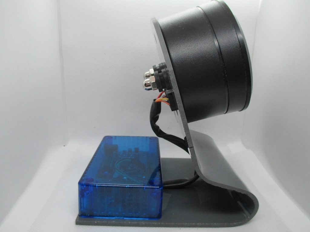
I made a stand out of some acrylic sheet and bent it to shape using a hot-air gun, along with some drilling and Dremmeling to fit the module to it. I used half of an ABS project case to fit over the control PCB. The set/adjust switch is a 12mm tactile switch glued into the top of the case with wires to the Gnd and S1 pads of H3 header on the PCB.
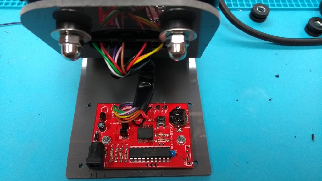
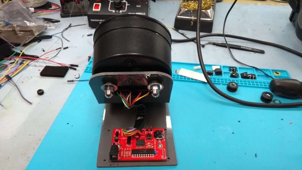
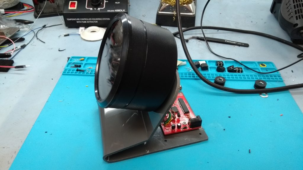
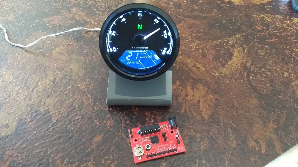
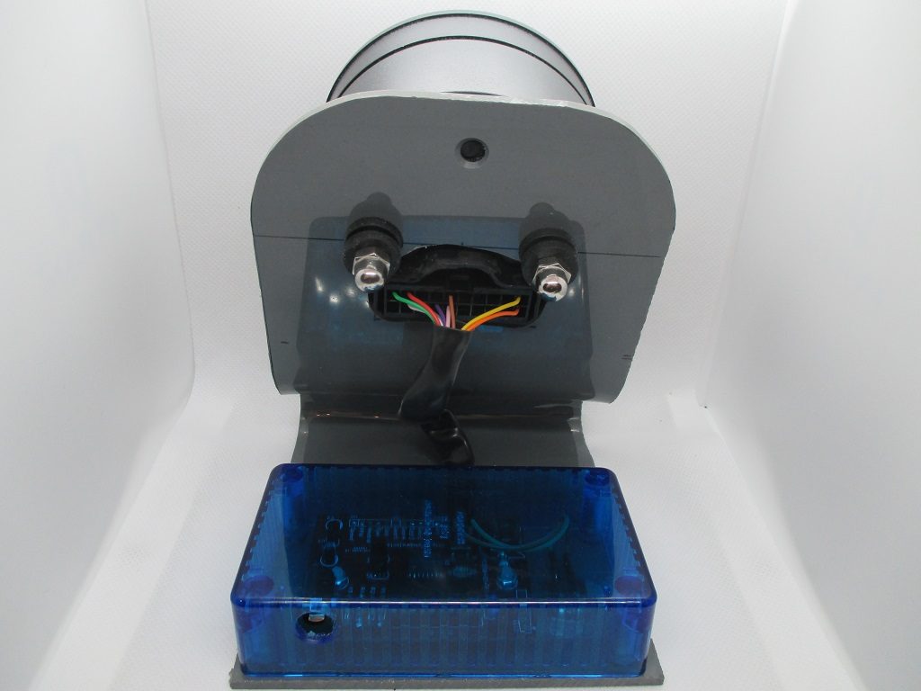
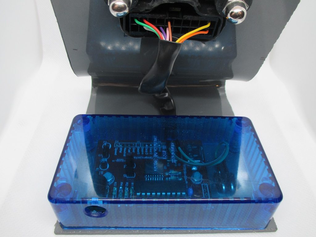
The photo’s below show the construction of a second clock. I made this using the left over acrylic sheet I used on the first one and the bottom of a Hammond transparent case, the top had gone missing long ago so it made use of it. For this one I put the time set switch on the base. I have a limited workshop, and not much imagination so I’m sure you could come up with a more creative way of presenting it 🙂

Connector and Cable Harness
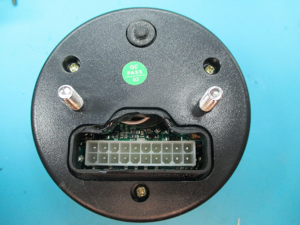
Both the instrument cluster modules I bought were supplied with a wiring harness, comprising a 20-pin connector going into the back of the unit itself, and four connectors on the tails.
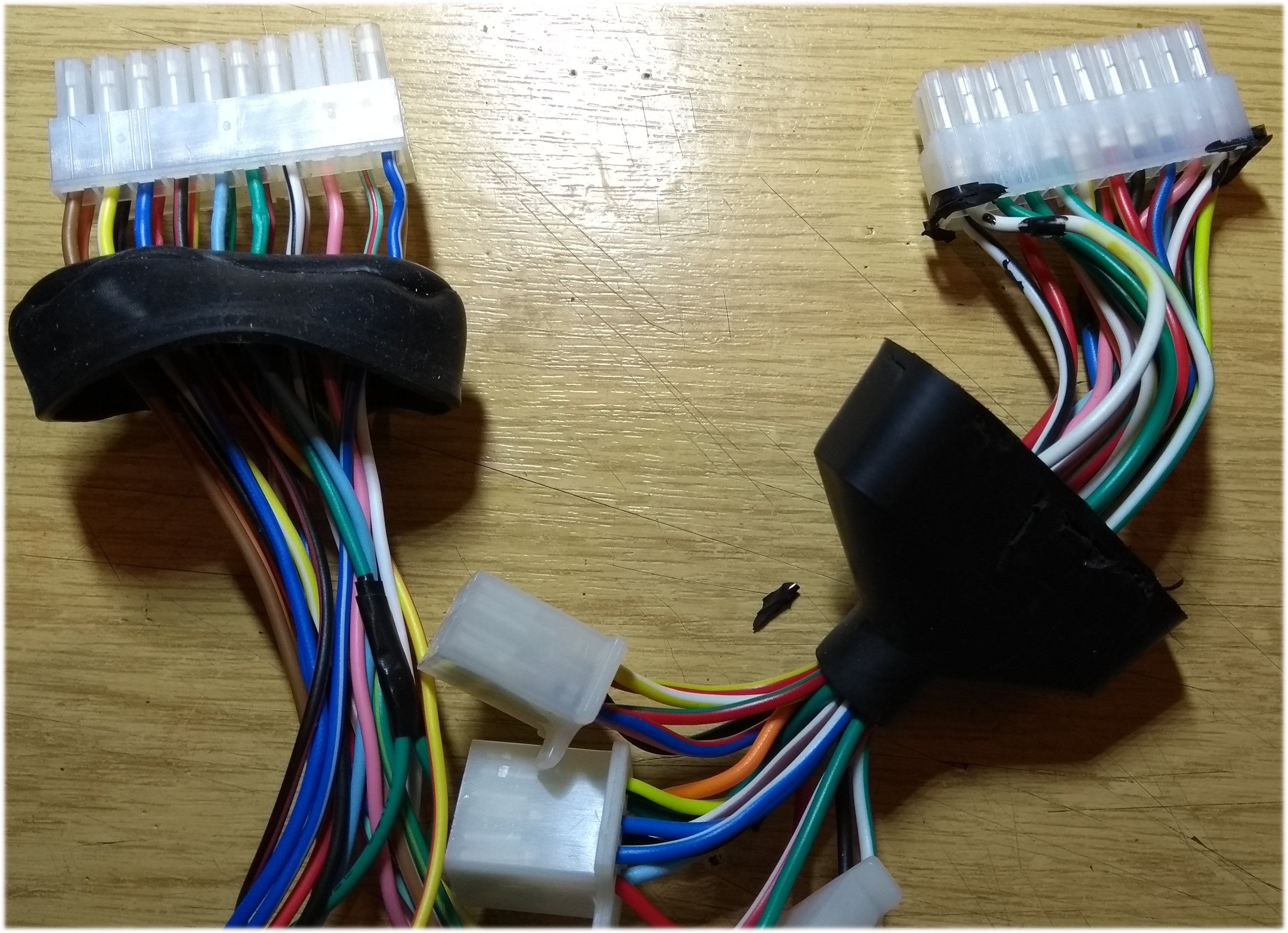
I didn’t use the supplied cable harness as I didn’t need all the connections presented on it, and the wire gauge used was a bit large and bulky. However, there is no reason why it can’t be used should you not want to make up a new connector.
The pin-out below left shows the 20-pin connector on the back of the instrument cluster (not the cable harness). The four connector tails are shown below right.
IMPORTANT: You should verify the connections on the instrument cluster you are using. DO NOT assume it is wired the same as the one shown here.
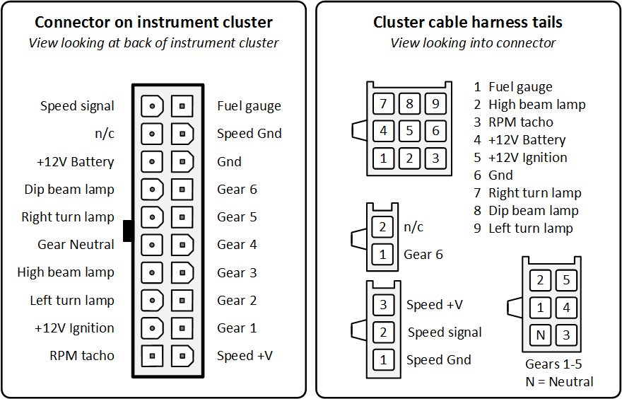
There are two connections to +12V supply; battery and ignition. On a motorbike, when you turn the ignition off and the engine stops, the tacho needle needs to return to zero, so it needs a permanent voltage to power the tacho needle stepper motor and control electronics to shutdown the unit. It seems to run fine with just the ‘+12V Ignition” powered, but I ran power to both connections anyway.
The Gear Neutral lamp is illuminated by pulling it to ground. The other lamps need to be driven high, they will illuminate from 5 volts but not very brightly, ideally they need 12 volts. To keep the control circuit as minimal as I could I chose not to use them.
Firmware
The code is written in Microchip XC8 2.05, and the MPLAB-X project files, HEX file and Python utility script can be download below.
The HEX file is ready to program and is the one used with my final version of the clock. It expects the following parameters to be set on the instrument cluster. It is also worth noting that I haven’t profiled the operation across a wide range of temperatures, testing was done in a room at 18-20oC.
- Units: MPH
- Tyre circumference 2.8M
- Pulses-per-wheel revoltion: 12
- Fuel gauge type: 2
- Engine: 2
Version 1.2 (29-04-2019)
MPLAB-X project files (zip)
Python script to generate minute data lookup table (zip)
Ready to program HEX file (zip)
Programming and Testing
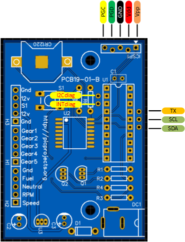
The ICSP header on the PCB has off-set holes. This allows a 5-pin header to be ‘jammed’ into the holes for programming without having to solder the header to the PCB.
There are five test points on the PCB. TX, SCL, SDA, I2Cdiag and INTdiag.
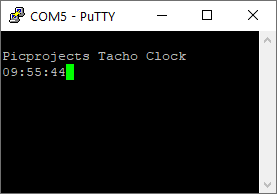
The time data read from the DS3231 is formatted as an ASCII string ‘hh:mm:ss’ and transmitted from the TX pin at 9600 baud, once per second. This can be used to verify the time display on the instrument cluster matches the actual time. You can send this data to a serial terminal emulator, such as PuTTY, or an oscilloscope that can do protocol decoding as shown in the examples below.

The I2C clock and data signals to the DS3231 RTC chip are presented at SCL and SDA test points.
If the PIC programs correctly but does nothing on the circuit, check the SCL signal. If this is ‘stuck’ low, it can indicate that either the SCL or SDA signals are not connecting to the DS3231 RTC chip. Also check that they aren’t shorting to an adjacent pin on the IC.
I2Cdiag & INTdiag signals are used for diagnostics.
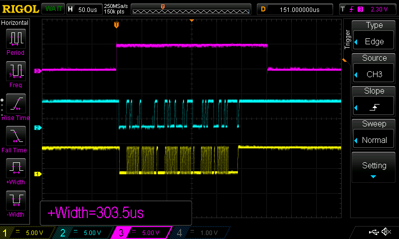
The I2C functions are blocking and don’t do error recovery. If there is a fault the control board may appear to be dead. The firmware Interrupt function will continue even if an I2C function is blocking, so there will always be a 40KHz signal on the INTdiag pin if there is any life in the PIC16F18345. Example of this signal is shown below
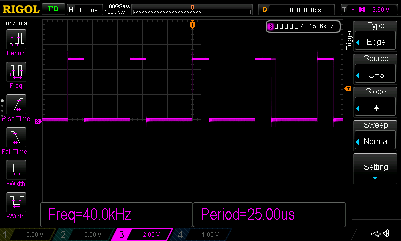
Trigger on the rising edge. There will be some jitter on the falling edge depending on how long the code takes to execute inside the handler function. This is normal
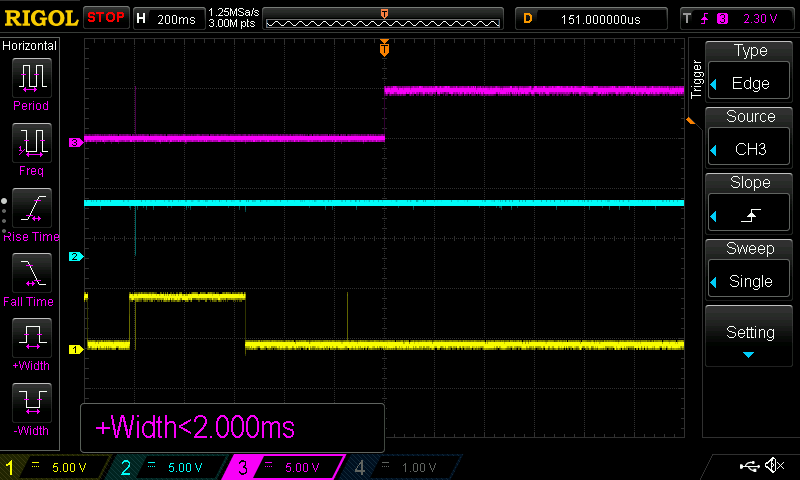
If I2Cdiag is static and logic high an I2C function has hung up which indicates a problem accessing the DS3231 RTC device over the I2C bus. Examples of normal and hung states are shown below.
– CH3 I2Cdiag
– CH2 SDA
– CH1 SCL
– CH3 I2Cdiag
– CH2 SDA
– CH1 SCL
Tuning Speed Data
Since building two of these clocks I’ve had a couple of occasions when they were powered off for a few hours. When this has happened the parameters for wheel size / sensor pulse / engine cyclinders in the speedomoter module are lost and the clock then displays incorrectly.
To fix it you only need to reconfigure the speedometer module settings back to the required values. It’s not a fault with the clock module itself.
The clock uses the speed display on the LCD section of the instrument to display the time minutes. This requires the control board to generate a signal simulating the output from a wheel speed sensor. The instrument cluster has parameters for wheel circumference and number of sensor pulses per wheel revolution. Knowing these and with a bit of maths, we can calulate the signal frequency required to display the speeds from 1MPH to 59MPH, which correspond to minutes 1 to 59. Minute 0 is easy, just don’t send any signal.
Since the instrument was designed as a speedometer not a clock it tends to over-read the speed. In the real world you want this so you won’t get a speeding ticket. We need it to display the minutes accurately, reading 1mph resolution of speed predictably – something the instrument wasn’t necessarily designed to do.
However, with a bit of empirical testing and tweaking of parameters, it should be possible to get it working fairly well. I found that to get the units I bought working reliably across speeds from 1 – 59MPH (thats 1 to 59 minutes) it needed the largest wheel diameter supported and the highest number of sensor pulses per wheel revolution. One of the units I tested with only supported 2.5M circumference and 9 pulses maximum and this never worked reliably. The second and third I tested allowed settings of 2.8M and 12 pulses and with these settings it worked consistently.
To make it easy to generate and test look-up table data for the speed/minutes I wrote a python script that outputs a C file containing an array like the example below.
#include <stdint.h>
// Lookup table with NCO1 increment data to drive speedometer
// This file is generated by Python script "RevClockNcoMinData.py"
const uint16_t SPEED[] = {
   0,   50,  100,  151,  201,  251,  301,  352,  402,  452,
 502,  525,  573,  620,  668,  716,  763,  811,  859,  907,
 954, 1002, 1050, 1097, 1145, 1193, 1241, 1288, 1336, 1384,
1431, 1479, 1527, 1575, 1622, 1670, 1718, 1765, 1813, 1861,
1909, 1956, 2004, 2052, 2099, 2147, 2195, 2242, 2290, 2338,
2386, 2433, 2481, 2529, 2576, 2624, 2672, 2720, 2767, 2815
};
The python script used to generate the data has four parameters that you can adjust to get accurate translation of speed to a display of the time minutes. I’ve not shown the whole script here, just the section with the parameters you need to customise. They are described in detail below. If you download the MPLABX project file, the python script can be found in the root of the project folder, when you run it it will update speed-data.c and you can just recompile the C source code.
# ================================================================
# Calculate NCO increment value data for RevCounter Clock Project
# Picprojects
# 17/04/2019
# for python 3.6+
# ================================================================


# ================================================================
# Set these parameters to match settings on the instrument cluster
# Setting the largest wheel circumference and highest number of
# pulses per wheel revolution the instrument allows seems to give
# best results.
# ----------------------------------------------------------------
# Tyre circumference set on instrument cluster in Metres
circumference = 2.8
#
# Pulses per wheel revolution set on instrument cluster
pulse_per_rev = 12
#
# Adjust calculated speed to compensate for speedo error
error_adjust = 0.95
#
# Only apply error adjust for speeds above this
error_adjust_above = 10
#
# ================================================================
line 16. circumference: Set to match value configured on the instrument cluster
line 19. pulse_per_rev: Set to match value configured on the instrument cluster
line 22. error_adjust: Empirical value, adjust until displayed minutes match RTC time. Because the instrument over-reads speed by design the calculated speed is multiplied by this value to get the adjusted value for the lookup table.
line 25. error_adjust_above: Empirical value, for speeds above this value apply error_ adjust. For speeds below about 10MPH the displayed speed may be correct and therefore no error adjustment is needed at these lower speeds.
Operation
Nothing complicated with this clock, it just tells the time. All you have to do is set the time and leave it to it.
To set the time:
- Press and hold switch S1 until display shows “Gear 1” then release.
- Press S1 repeatedly to set the hour (1-12) on the tacho needle.
- Press and hold S1 until display shows “Gear 2” then release.
- Press S1 repeatedly to set the tens-of-minutes (0-5) on the tacho needle.
- Press and hold S1 until display shows “Gear 3” then release.
- Press S1 repeatedly to set the minutes (0-9) on the tacho needle.
- Press S1 and hold until display shows “Gear 5”, the time is set, seconds are reset to 0 and clock returns to normal time display function.
I don’t like having the gear number showing when it’s not in time setting mode, I think it clutters the display. If this also bothers you then you can just leave the ‘Gear 5’ wire disconnected so although the PIC is driving the output, it’s simply not connected to the instrument cluster – easy.
When the clock is in normal mode, a short press of switch S1 toggles the ‘Neutral’ light on / off.
The fuel gauge should also ‘fill’ on even minutes and ’empty’ on odd minutes. This is just for animated effect, don’t read too much into it.