Since I stopped selling kits in 2016 I’ve had a small but steady stream of enquires about the Race Start Controller project. Since I had no stock of the original PCB for the project I was unable to supply kits or pre-assembled boards.
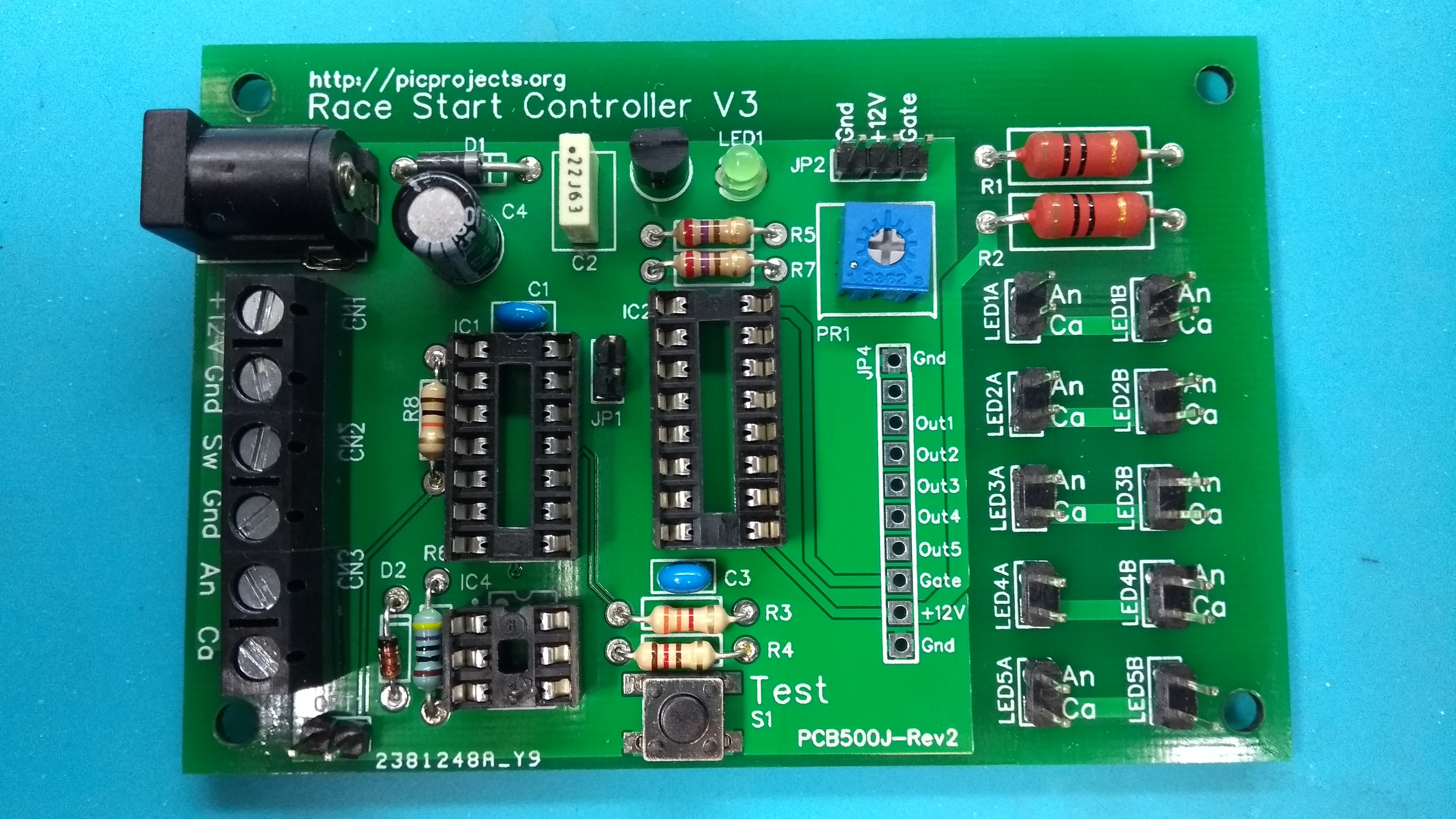
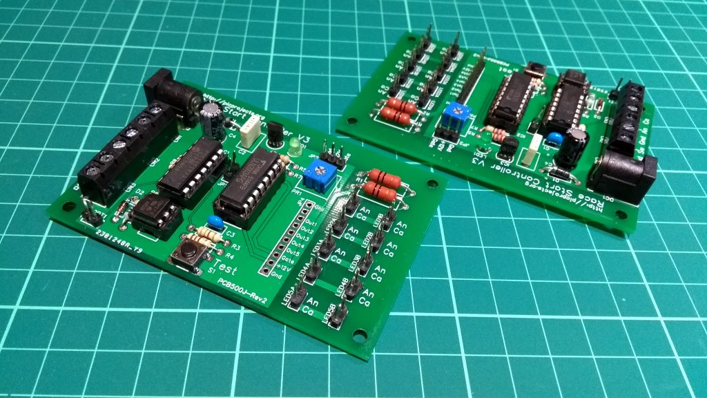
After yet another enquiry I decided to revisit the project, lay out a new PCB and have a small batch of boards manufactured. It’s essentialy the same project, uses the same firmware and has the same functionality as the original but I’ve taken the opportunity to add a new header that will make it easier to connect relay modules in place of the orginal LED cluster modules. This was something quite a few buyers of the original board had wanted to do, so it made sense to include this. The new PCB is slightly larger than the original and double-sided which makes assembly easier.
A revised schematic for the new PCB can be downloaded below. The actual circuit is identical to the original with the addition of the JP4 header, R8 and a 2-pin header, OPT1. All connections and operation are the same as the original project (see here).
The original project page also has links to download the firmware for the PIC16F1823.
Operation and timing diagrams PDF
A revised schematic for the new PCB can be downloaded below. I’ve tried to keep the component and connector numbering the same as the original PCB


Buy one
I’m no longer selling kits, or complete boards for this project.
The PCB design is availble free on the EasyEDA website and from there you can order the board direct from JLC PCB.
Firmware HEX file for the 16F1823 PIC microctroller can be download from here:
https://picprojects.org/projects/f1lights/firmware/PRG500_gridstartRevD_524_1F43.hex
The PCB design is on the EasyEDA website
If you want to have your own boards manufactured, open the PCB layout in the editor and click on the ![]() icon in the toolbar to generate the Gerber files.
icon in the toolbar to generate the Gerber files.
Quick Start Guide
Download the PDF for a one page quick start guide to the operation of the controller
Operating with Relays
The control board can directly drive the 12 volt Kingbright LED modules shown on the original project page (see here). However, if you want to control different LED modules, or lights with different voltages the board can be connected to a relay module, the relay outputs then switch the alternative lights.
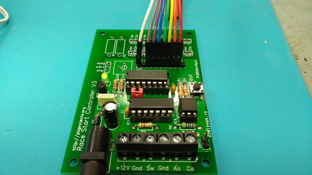
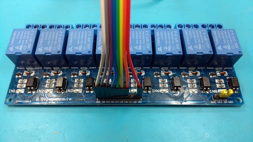
The image below shows the control board connected to an 8 channel, 12 volt, opto-coupled relay module. Only 6 of the 8 relays on the board are used. The modules are fairly cheap – the one shown was bought from a UK based seller for about £6.50 inc. shipping. These modules are readily availble on eBay and many other sites.
It is important to note that the outputs from the control board are active-low. This means the output connects to ground when it turns on. Therefore whatever relay module is used it must support active low inputs.

Connections from the control board are Gnd, 12 volts, 5 start light control signals and the gate signal. Connections in detail are shown in the images below. When the control board is connected to a relay module, a jumper must be fitted to the JP1 pin-header (see red jumper in the images below)