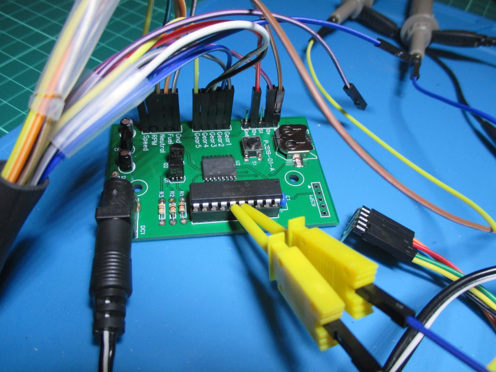
This is just a quick update to say I’ve been working on this steadily for the last few weeks. The PCB finally arrived earlier this week and I’ve got a board assembled and working.
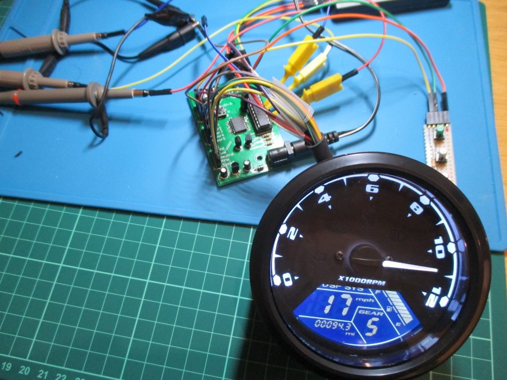
This project is proving somewhat of a challenge. I’ve now bought two Universal LCD instrument clusters to test with and this is where things got interesting.
The second one I bought came without any instructions, I contacted the seller and they said sorry, we don’t have instructions for it. Now you might ask why did I need instructions for this one if I’d already got one? The answer is that while they look identical, the second unit is different, you enter setup mode in a different way, it configures differently although it has the same options and the 20 pin connector on the back of the unit is wired completely differently. The four connectors on the other end are wired the same but I’d bought some 20 pin connectors so I could make my own connector cable up. This second unit also seems to be more consistent at converting speed to minutes compared to the other one.
Anyway, I’m just working through what I hope are the last few little issues and a more detailed write up is coming…
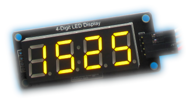
I recently got hold of some 7-segment LED modules that use the TM1637 LED drive controller IC. You can find these on eBay, Amazon and all the usual resellers of maker hardware. Since I had some ‘fun and games’ getting them working, I thought I’d share my findings here.
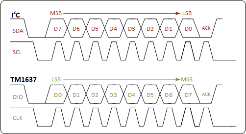
I2C it is not
The first thing to catch me out was the I2C interface that isn’t. The translated data sheet for the device describes communication with the TM1637 by means of a two-wire bus interface. At first glance it looks like an I2C interface, however the datasheet points out that “it is not equal to I2C bus protocol totally because there is no slave address“. Well that’s not too much of a problem, it does mean you can’t have any other devices on the bus but that’s not a show stopper.
What it doesn’t make clear is that it expects data to be sent LSB first, and this caught me out for a while. Standard I2C sends data MSB-to-LSB. If you’re bit-banging the interface it’s easy enough to reverse the bit order of data being shifted out, but if you want to use the PIC’s MSSP module then it’s going to send it MSB first, so you need to reverse the byte before loading the SSPxSR buffer register.
Bit ordering
For example the TM1637 Data command setting for ‘Write data to display register with automatic address adding‘ is 0b01000000 (0x40) so you need to load the SSPxSR register with 0b00000010 (0x20) so it arrives at the TM1637 LSB first.
Capacitors on the CLK & DIO lines
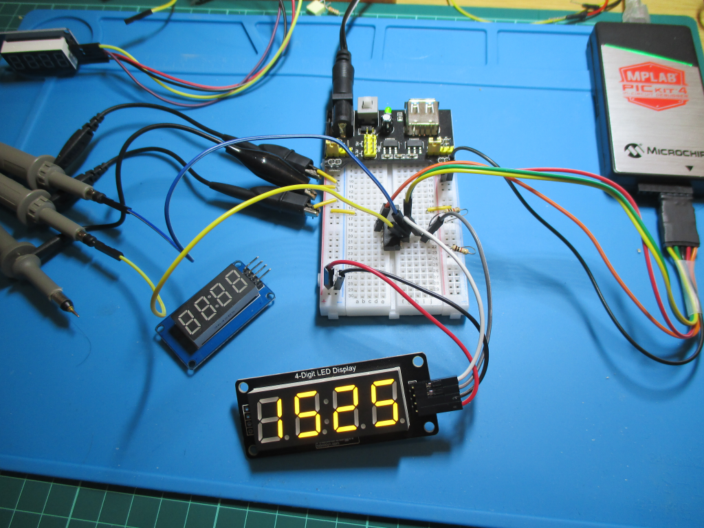
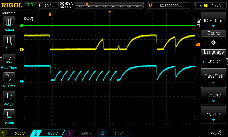
The next problem I had was not the TM1637 itself but one of the modules I’d bought. Whenever I’m developing stuff I like to hook up an oscilloscope to the hardware signals to see what’s happening. It can be a fast way to verify that things are doing what you expect, and it can save a lot of time troubleshooting when things aren’t working. In this case the control signals appeared to have large capacitive loading on them, at least the RobotDyn module did.
The I2C bus relies on pull-up resistors to pull the signals high, devices on the bus only drive it low. Instead of a nice sharp rising edge, what I was seeing was a perfect RC time-constant curve. I ended up adding 330ohm pull-up resistors to get it working at all, and at much reduced clock rate.
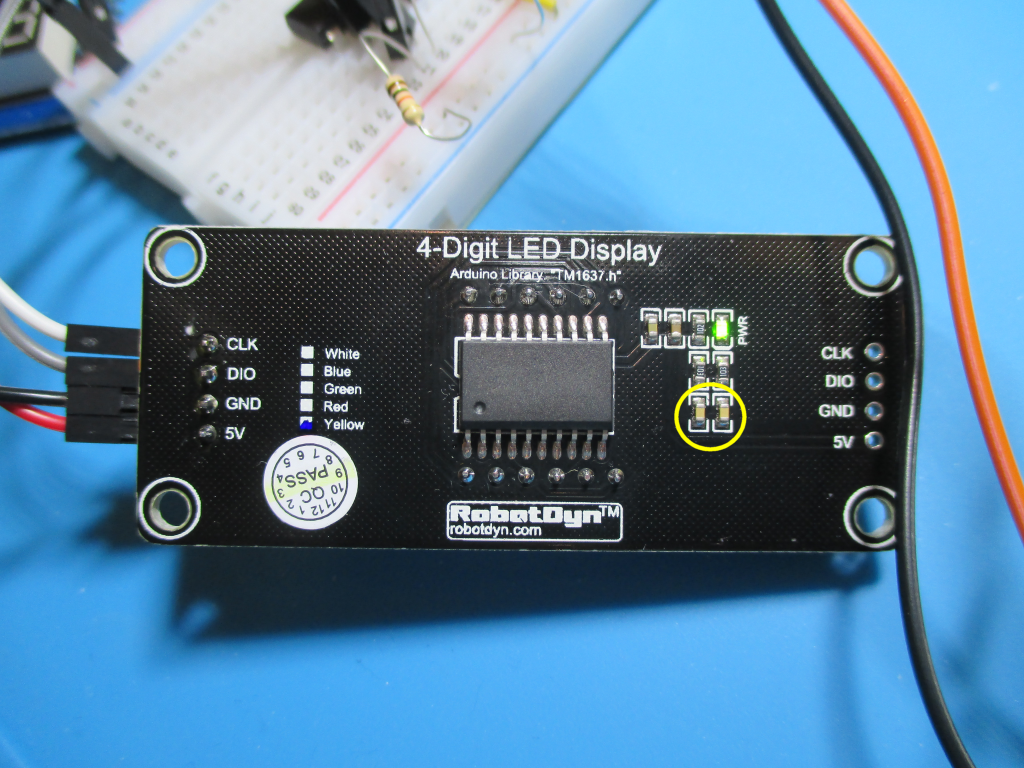
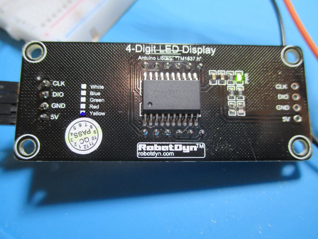
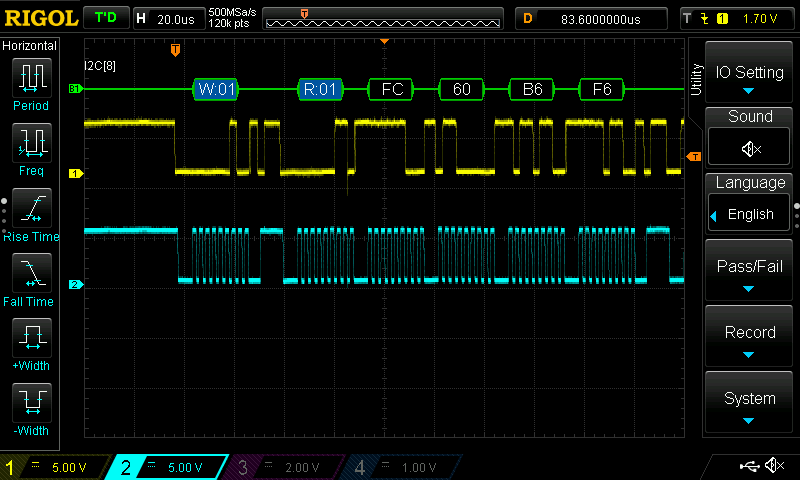
The datasheet for the TM1637 suggests using 100pF capacitors on the CLK and DIO lines, but what I was seeing was the effect of something much larger than that. In the end I found a schematic for the RobotDyn 4-digit LED Display I was using and it showed 10nF capacitors on the CLK and DIO lines. I decided to remove the capacitors completely and the display now works fine with a 400KHz I2C clock and the original 10K pull-up resistors fitted to the board.
In the pictures below I’ve highlighted the capacitors that need removing and the before and after signals on the oscilloscope.
10nF capacitors circled
with capacitors removed
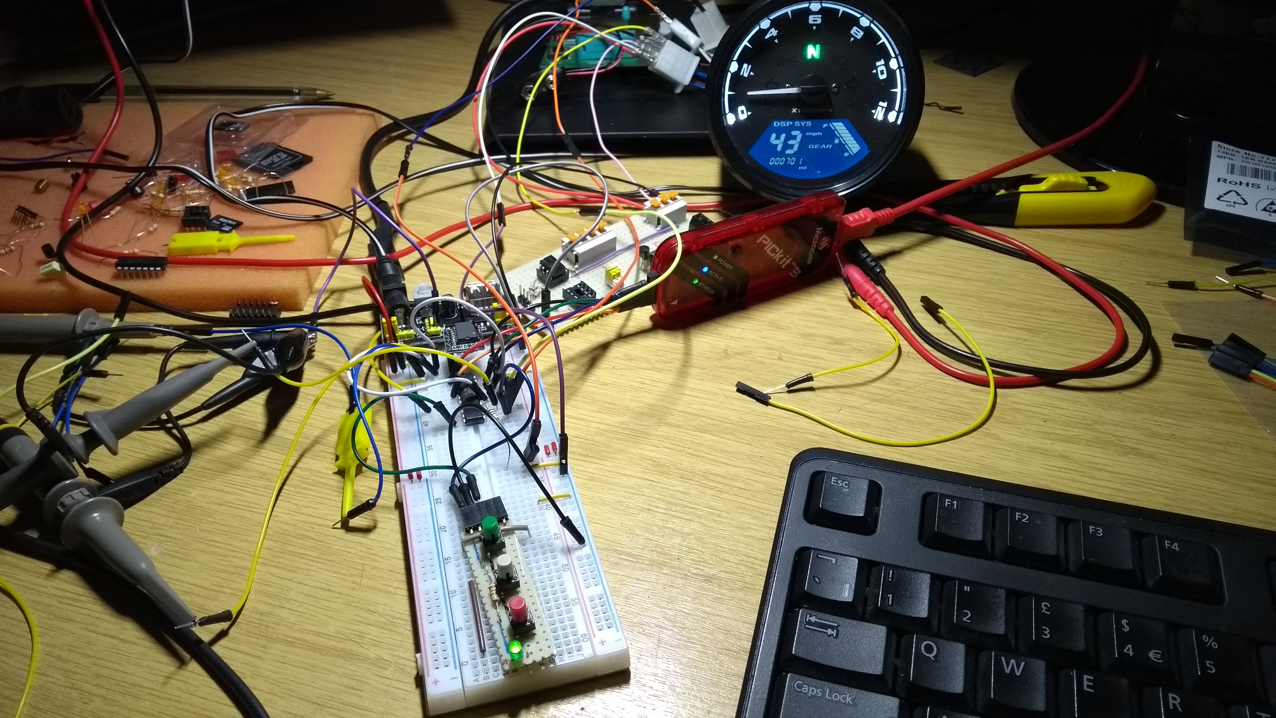
Test circuit, now working
With 10nF capacitors on CLK & DIO lines
After capacitors removed
Centre Colon
The modules I bought are 4 digit clock style LED displays with the centre colon. The decimal points on each digit aren’t conneced, however the centre colon is connected to the SEGment8 output of digit 2 (Display address C1H in the datasheet). I guess this wiring is specific to the modules I bought, but both the RobotDyn module and a couple of no-name modules had the colon connected the same way.
The code I wrote for testing can be download below, it’s the packaged MPLAB X project, with source code.
I recently saw a feature on the Hackaday website for a clock that had been made from a multifunction instrument cluster using the analogue tachometer for the hours and digital speed readout for minutes. This was implemented using an Arduino, so I thought perhaps I could do something using a PIC. I found the gauges on eBay, they’re usually described something like “LCD Digital Motorcycle Speedometer” and sell for around 20GBP so I bought one to play with.
Development setup
Once I’d worked out what signals and voltages it required to operate I put things together on the breadboard with a PIC16F1823. Early on I figured it would need more I/O pins so got hold of some PIC16F18345 to work with.
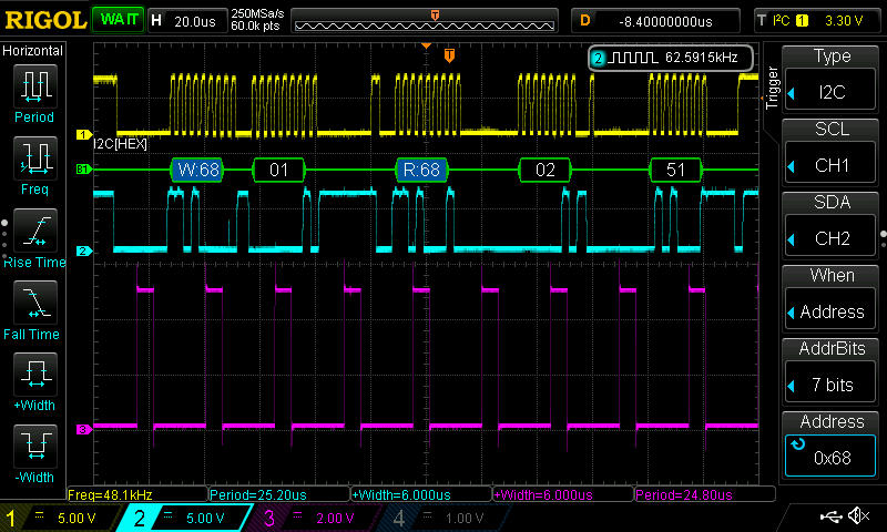
Reading the minutes and hours from DS3231 over I2C bus
For the actual time keeping I’ve used a DS3231 RTC. I found some really cheap modules on banggood.com, shipped from China. Three modules worked out cheaper than buying one from a UK distributor. I don’t know if they’re genuine parts or not but they certainly keep time accurately.
I’ve now got the software pretty much complete using Microchip XC8 C compiler and also a PCB designed and on order from JLC PCB. Once all the bits are together and working I’ll do an update here with all the code and other information.
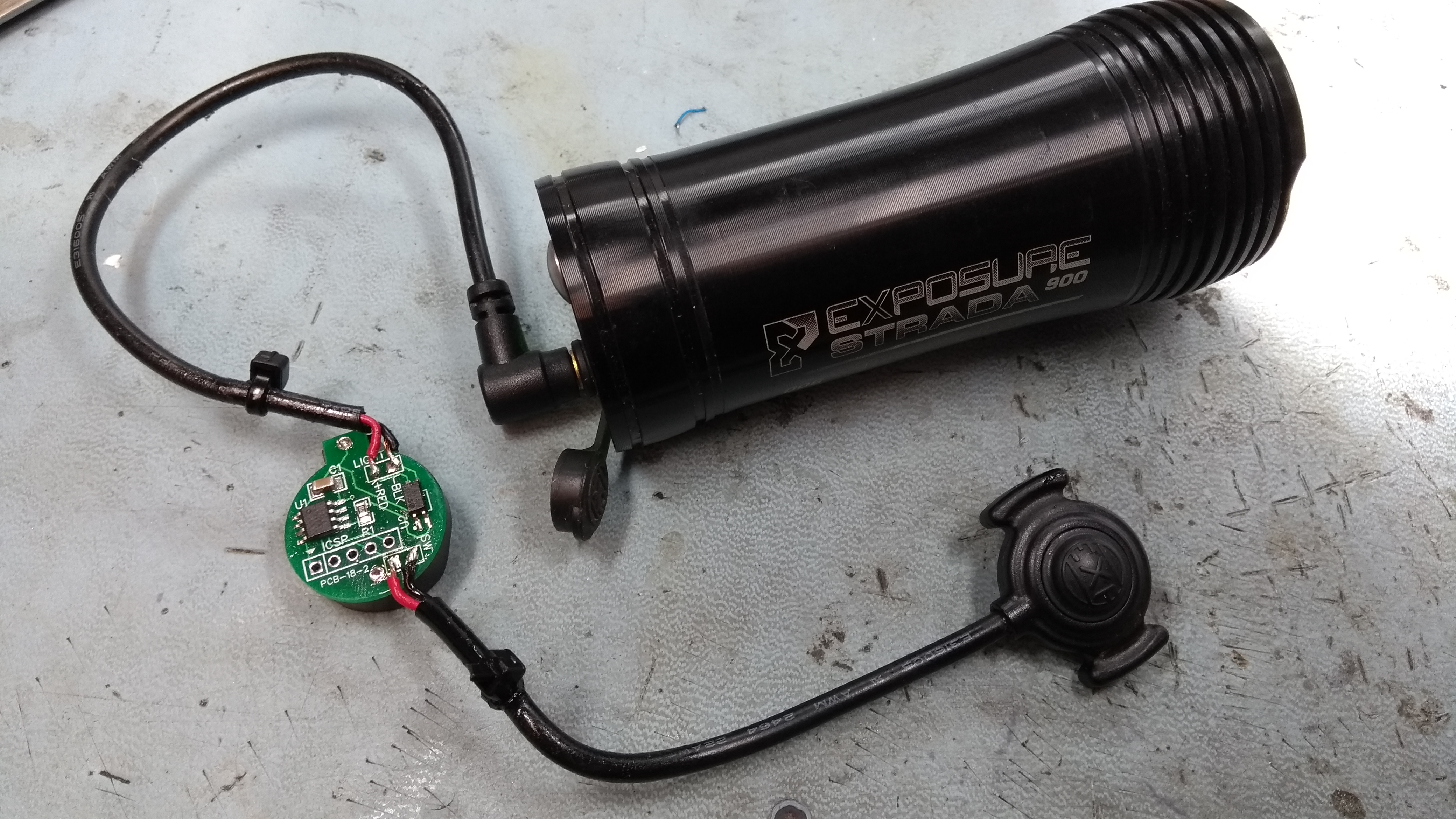
In mid December last year I put together a switch conditioner circuit to address the issue I had with the Exposure Strada light I was using on my MTB. I ran it on the bike until the end of March 2018 when the evenings had enough daylight not to need lights.
So how did it perform? The weather in the UK at the beginning of 2018 was cold, wet and even a couple of weeks of snow. Throughout the three months of use in the cold and rain it worked reliably. I had no more issues with either the switch not responding or going into flash mode, in a fact it eliminated all the issues I had previously. It’s still running on the CR2025 battery that was fitted in December and that battery wasn’t new.
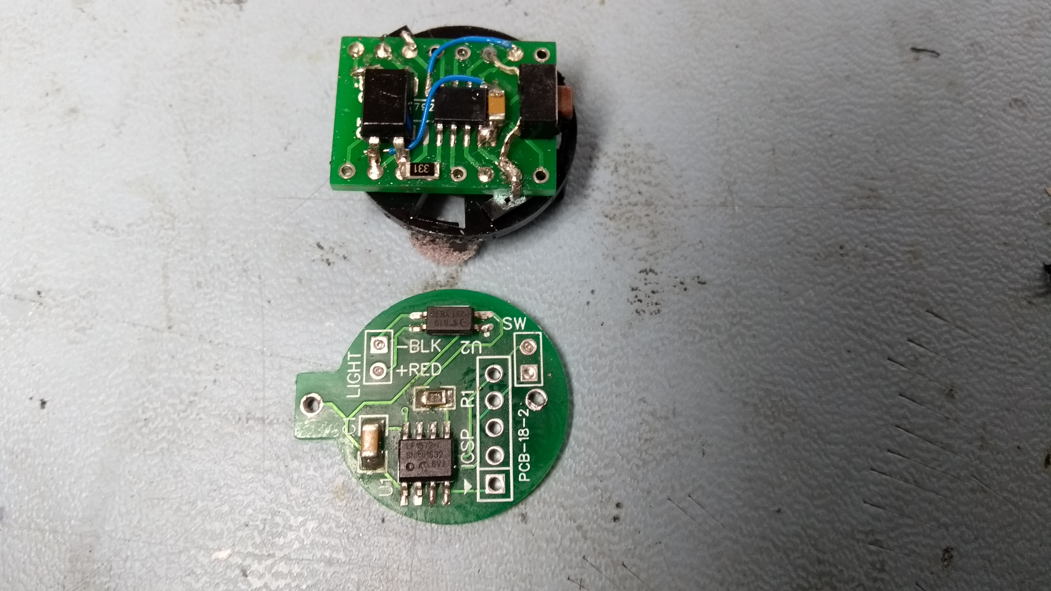
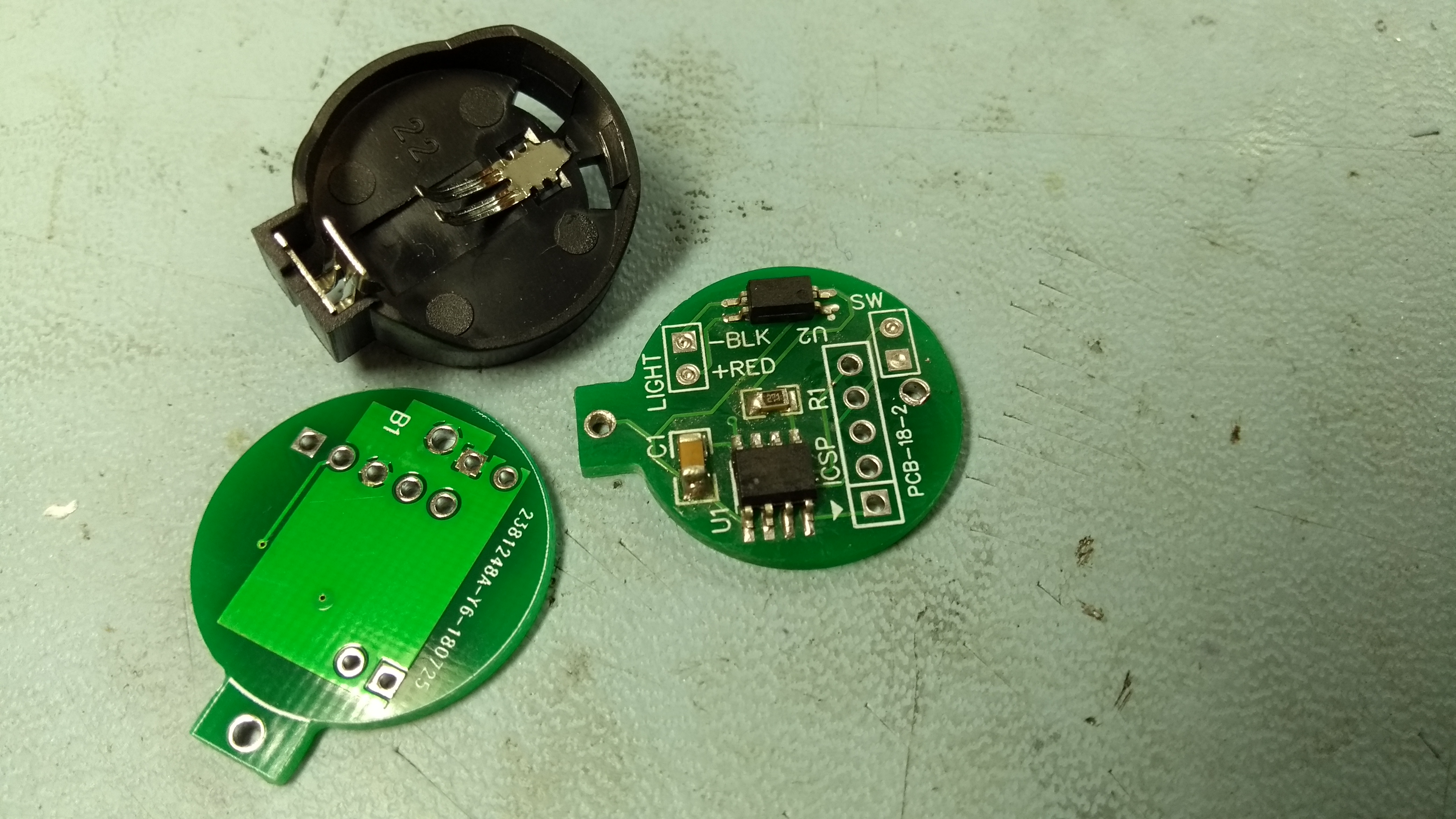
The original version was assembled on an SMD-to-DIP adapter PCB and was a bit of a hack. Since it worked so well I designed a PCB for it which has the same profile as the CR2025/2032 battery holder. The photo below shows the new PCB below next to the original hack. Since I had 10 boards made I assembled the first one for testing before making up a second to go on the bike.
The PCB was designed using EasyEDA and I had 10 boards manufactured by JLC PCB for $2 + shipping which worked out at about £6.00 for the boards shipped to the UK.
The new PCB has been profiled to fit under the coin cell battery holder and has an ICSP header so the PIC micro-controller can be programmed on the PCB.
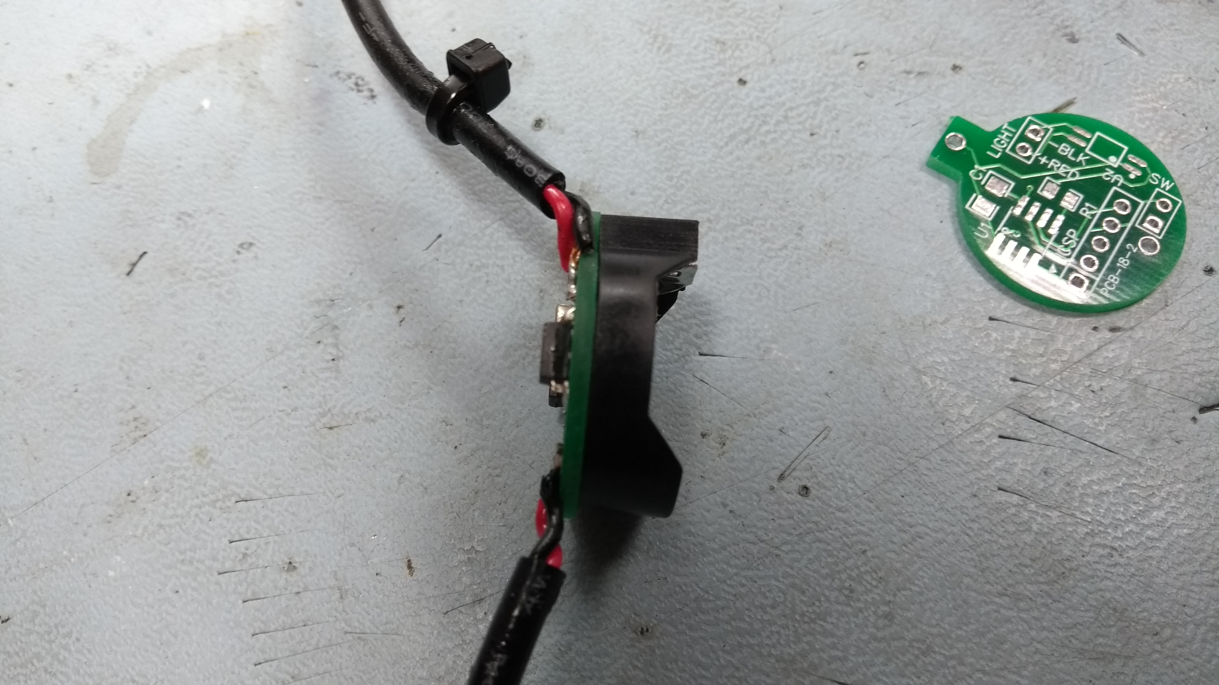
The assembled PCB was sprayed with conformal coating to protect from moisture and fitted into the same case I used for the original circuit. Cable ties provide strain relief, the pink foam stops it moving inside the case, and some silicone grease was used between the case and cover.
You can find the schematic and PCB Gerber files along with a link to order your own boards from JLC PCB below. The MPLABX source code and HEX firmware file is also available on the easyEDA site.
I can’t remember when I originally started the Picprojects website, I had some content on a personal website back around 2004 and the ‘Way Back Machine’ Internet Archive has a web page from May 2009 on the picprojects.org domain so it predates that for sure.
Back then I was using FrontPage Express to create the content. I know that wasn’t a great application to develop a website with even then, but that’s what I had access to. As more projects got added and the site got larger it got to the point where it should really have been migrated to something better but I had no desire to spend the time and effort revamping the whole site.
I like cycling and regularly go out after work for a ride, so over the winter I use an Exposure Strada front light. This particular light has a multi-function ‘SmartPort‘ that allows it to be charged, or power other devices, or by connecting a simple remote push button switch you can control the light output power, change from constant to flashing mode, and turn it off and on.