
Switch conditioner using a PIC12LF1522
I like cycling and regularly go out after work for a ride, so over the winter I use an Exposure Strada front light. This particular light has a multi-function ‘SmartPort‘ that allows it to be charged, or power other devices, or by connecting a simple remote push button switch you can control the light output power, change from constant to flashing mode, and turn it off and on.
The remote switch can be located on the handlebars making it easy to operate without taking your hand off the bars which is good. The switch has multiple functions depending on how long it’s held down and I find that in practice it doesn’t work as well as it might – frankly it can get quite frustrating – here’s why:
The switch needs to be pressed for at least 140mS before the light changes output power. You can just give it a firm push, but have to be careful not to hold it over 400mS since that puts it into flashing mode. So if you don’t press it long enough it doesn’t change mode, but press it too long and it goes into flash mode. Worse than that, you give a quick press, doesn’t register, press again and it registers as one longer press putting it in flash mode. If you’re sitting with it in the house and trying it it seems to work reasonably well, but put it on the bike, throw in a cold night, gloves and your attention to the road ahead and it just gets plain irritating.

Development test board
So during my last few rides I started thinking – could I do something to fix the issues I have with it? I started with a small circuit using a PIC12F1822 and an opto-isolator to interface to the ‘SmartPort’ on the light. I created some simple code to allow me to test different pulse durations to simulate pressing the switch. I was then able to establish the minimum time needed to switch modes, and the minimum time before it would change to flash mode. Turns out it needs a simulated switch actuation of at least ~140mS to register as pressed and ~400mS or longer to change to flash mode. Two pulses over 140mS with a gap of less than 140mS can cause it to go into flashing mode
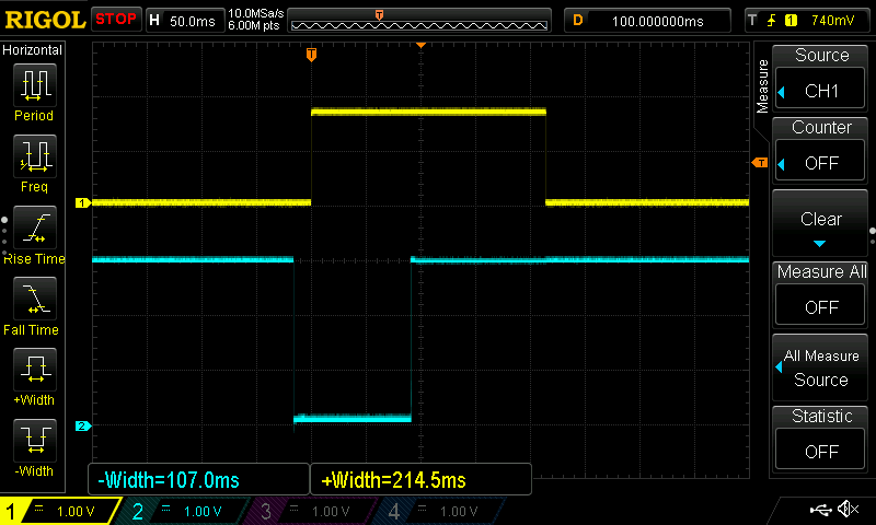
The four screen captures below were made on the test board while investigating the required pulse widths and development of the code. The yellow trace is the ‘active high’ signal from the PIC output to the opto-isolator which the light sees as a ‘pressed’ switch.
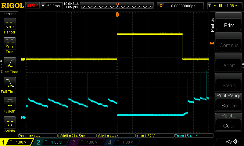 This capture shows the signal at the ‘SmartPort’ when the light is switched off. | 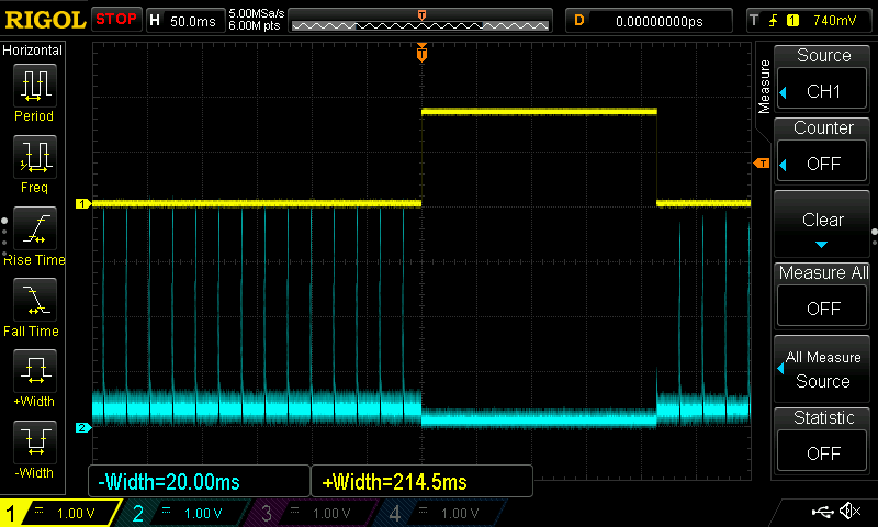 This capture shows the signal at the ‘SmartPort’ when the light is switched on. |
 This capture shows a single press of the switch and the ‘conditioned’ output. | 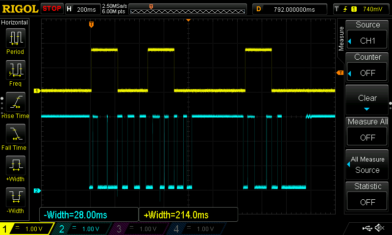 This capture shows the input switch being pressed rapidly and the ‘conditioned’ output |
So the switch conditioner code makes even a very quick press of the switch generate a fixed 229mS effective press at the opto-isolator output, with a further 146mS hold-off. ( I tweaked the final timings from those shown in ‘scope traces above ). A press-of-the-switch of at least 15mS will always initiate a 229mS activation to make the light change power level. The hold-off delay prevents double presses being seen as a long press and it won’t toggle if the switch is held down since it must be released before it will activate again.
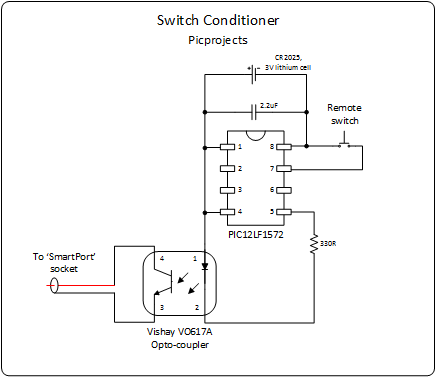
For the final circuit shown here I used a 12LF1572, mainly because these were cheap for a pack of 10 and I couldn’t get a 12LF1822. I wanted the LF part because it will be permanently powered from a single CR2025 lithium coin cell. The PIC sleeps between presses of the switch and consumes around 50nA – that’s what the datasheets says anyway, it is certainly too low to even register on the μA range of my multimeter.
I assembled the final circuit onto a 16 way SOIC to DIP adapter board that I had to hand, with a coin cell battery holder underneath. The photo below shows it connected to the PICkit3 for programming. Not the best way to do it but I decided to use a different input pin for the switch so needed to reprogram the PIC – it got the job done.

Switch Conditioner final circuit
In the photo below the complete circuit and battery are fitted into a small box and held to the bars with a velcro strap, the push button is on the left of the bars, the light isn’t fitted but goes on the ‘V’ shaped bracket to the right of the box.

Boxed and attached to the bike
I’ve been using this now for a few evening rides and it works well, it consistently changes from high to low, or low to high power – never goes into flash mode, always operates even with the quickest press of the switch.
The hardware for the circuit is very simple, I used SMD parts but you could make this with thru-hole components and it would still be very compact. You can use any generic opto-isolator – I used a CNY17-3 in the test circuit and the VO617 in the final version. I specifically used an opto-isolator rather than an open-collector transistor because the ‘SmartPort’ on the light ‘polls’ to see if it needs to supply power to a load. I felt it best to keep the light electrically isolated from the control circuit. For the switch I just used the original remote switch, cut the cable in half and then connected it either side of the circuit.
You can get the code for this project below. I used Microchip’s MPLAB Xpress Cloud-based IDE to develop the code and a PICkit3 to program the PIC.
The code actually implements two switch inputs, one generates a short mode change pulse and the other a longer pulse to put it into flashing mode. I have no practical need to quickly put it into flashing mode during a ride so the second switch isn’t connected – it can always be activated from a switch on the light itself if needed. The program is written in assembler, I’ve put plenty of notes/comments in it if you want to modify it. The switch active and hold-off durations can easily be tweaked by changing program constants before assembling.