This is not a PIC micro related post, nevertheless I think it is interesting.
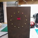
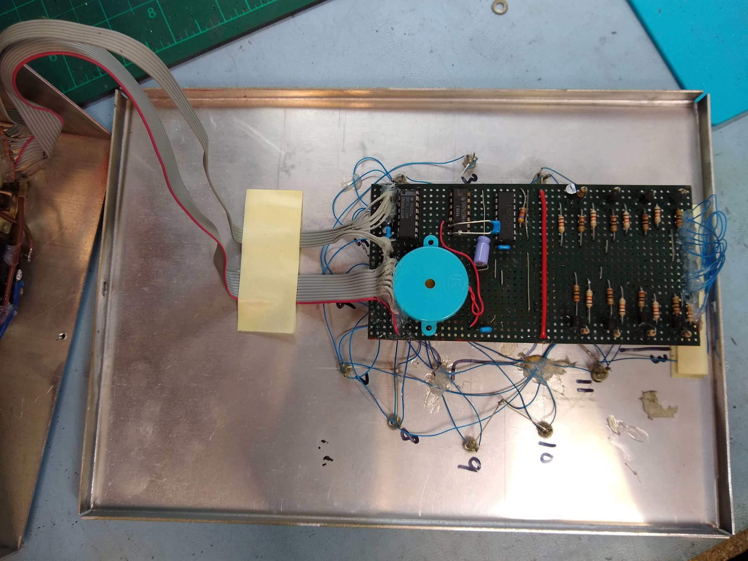
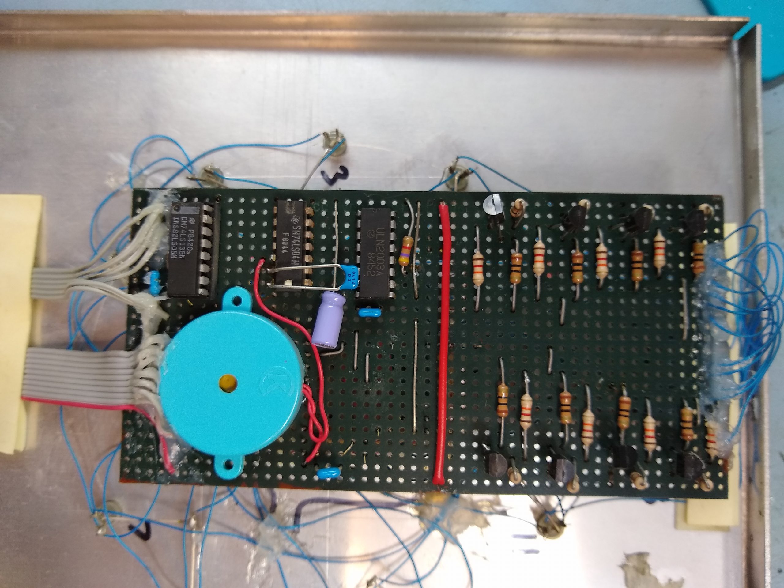
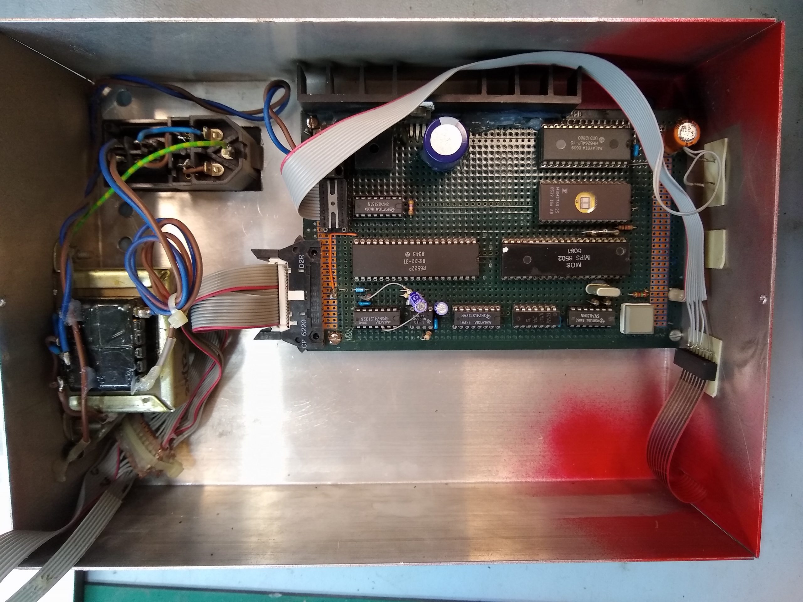
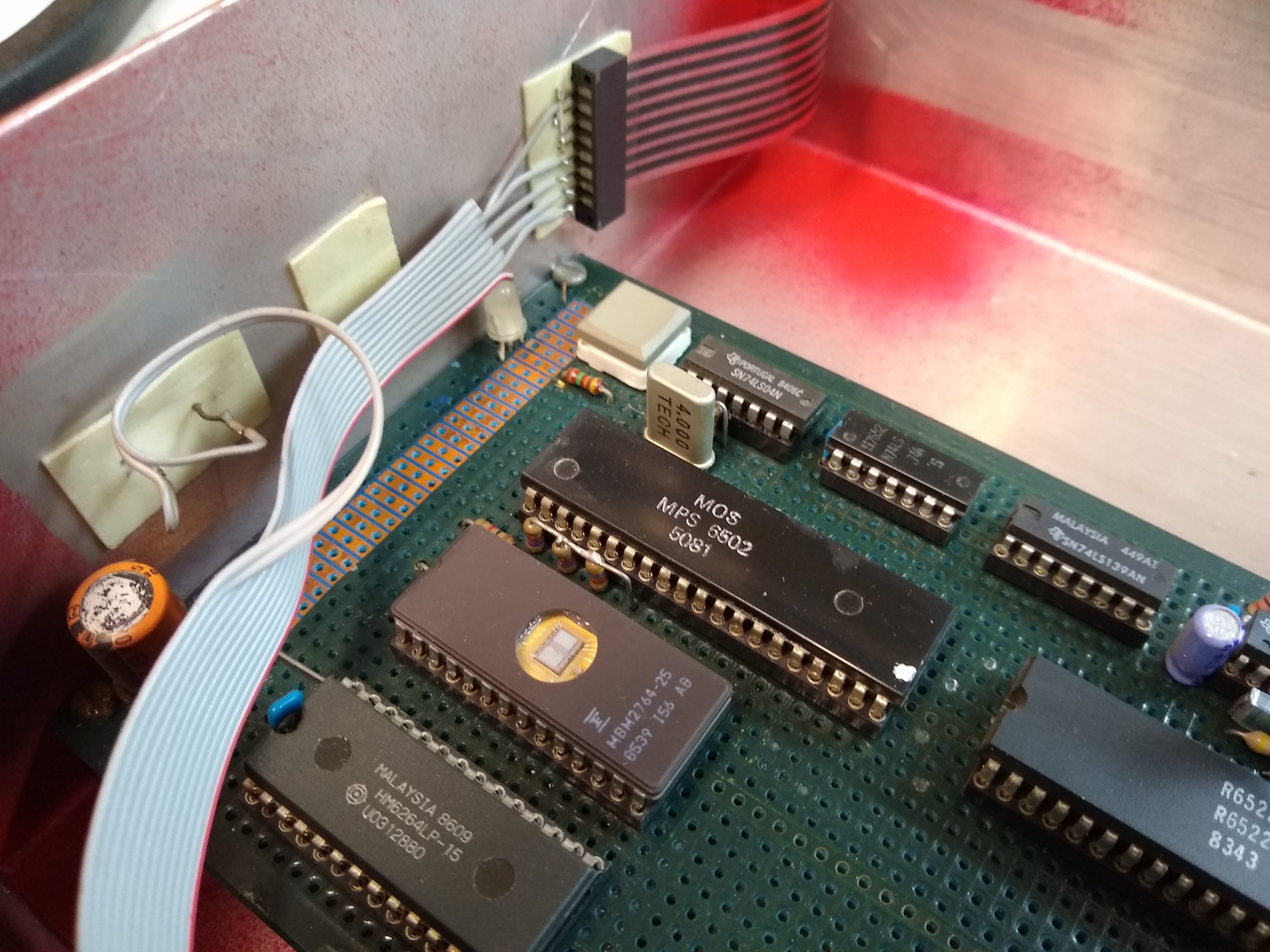
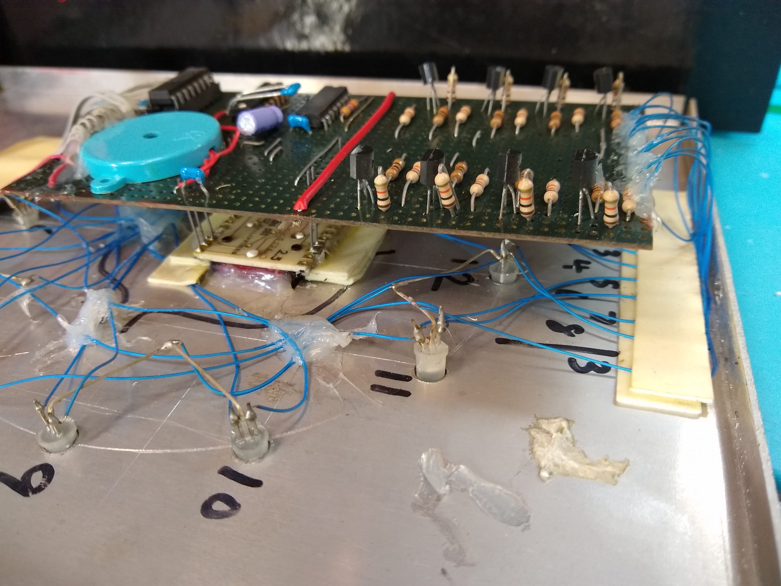
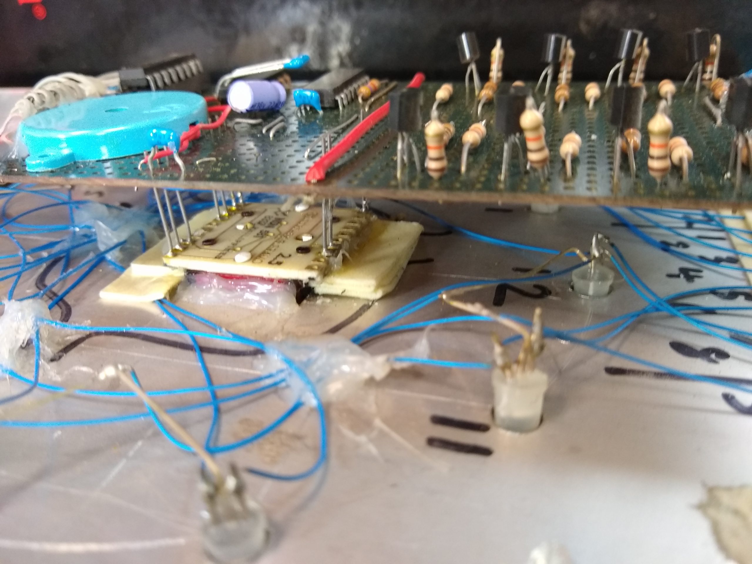
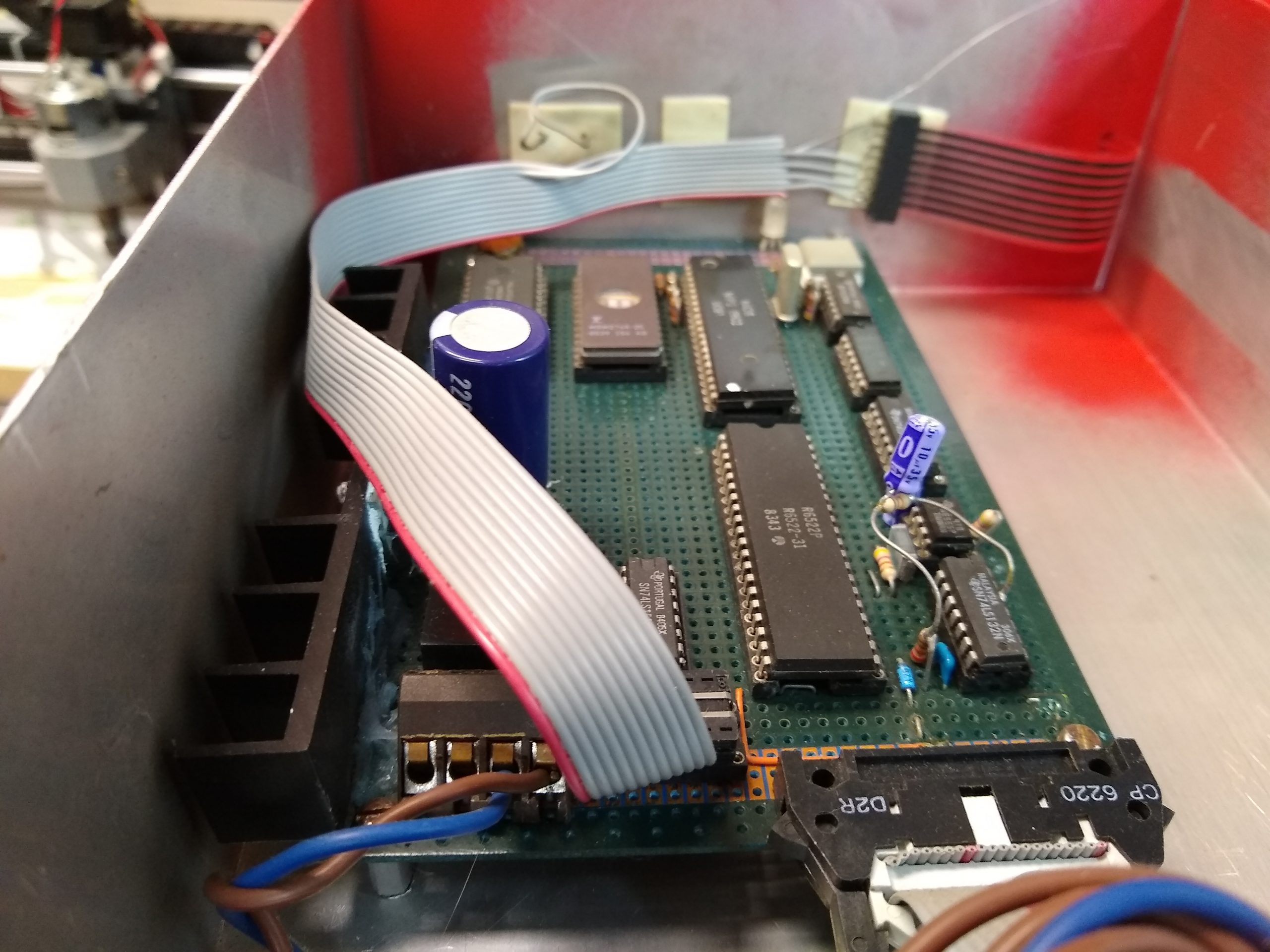
This was a clock I built around 1985/86 using a 6502 microprocessor. It was the precursor to the ‘Record Time Clocks‘ I went on to build using an Intel 8748 microcontroller and eventually the PIC microcontroller based ‘Record Clock Redux‘ project.
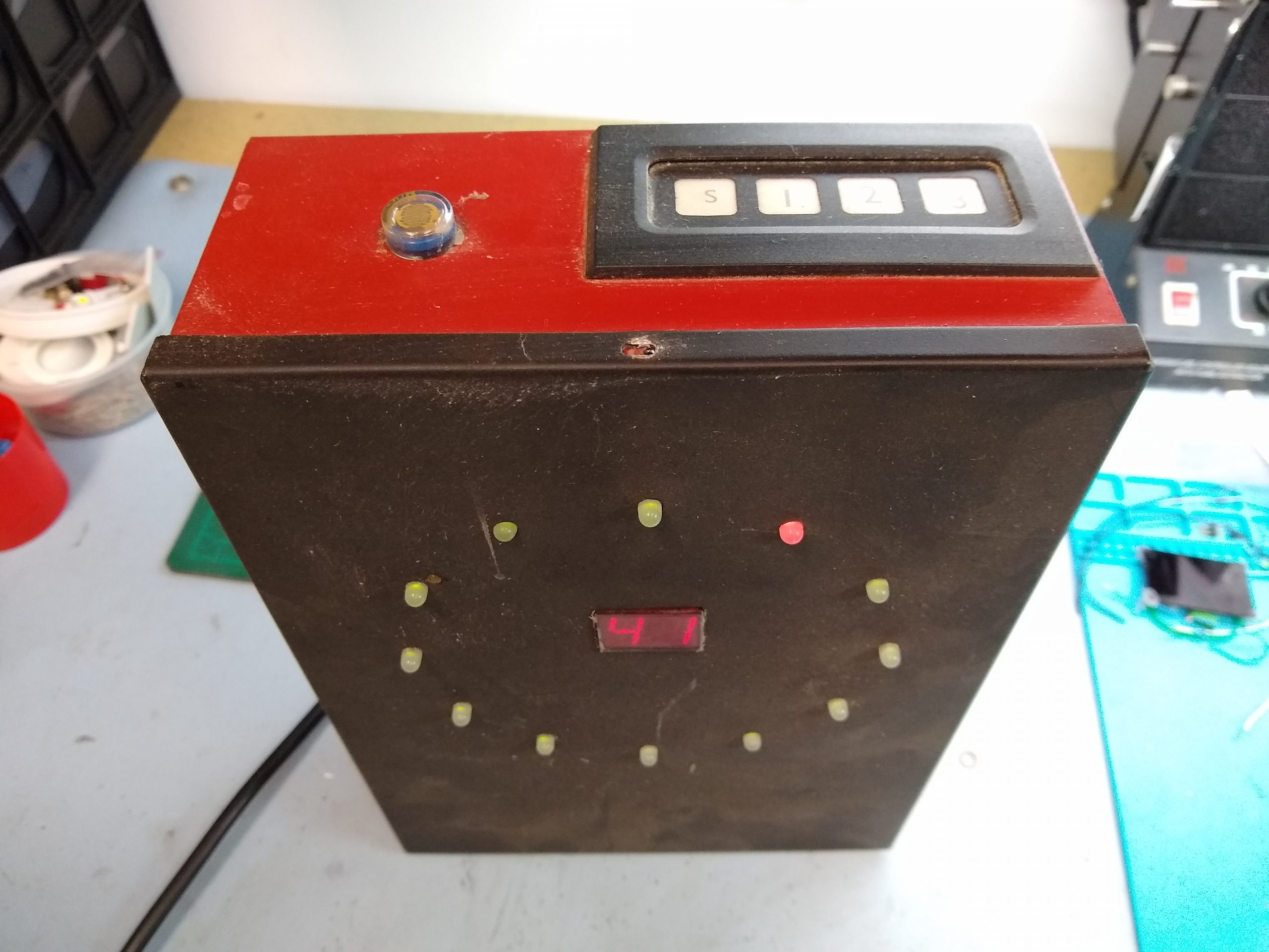
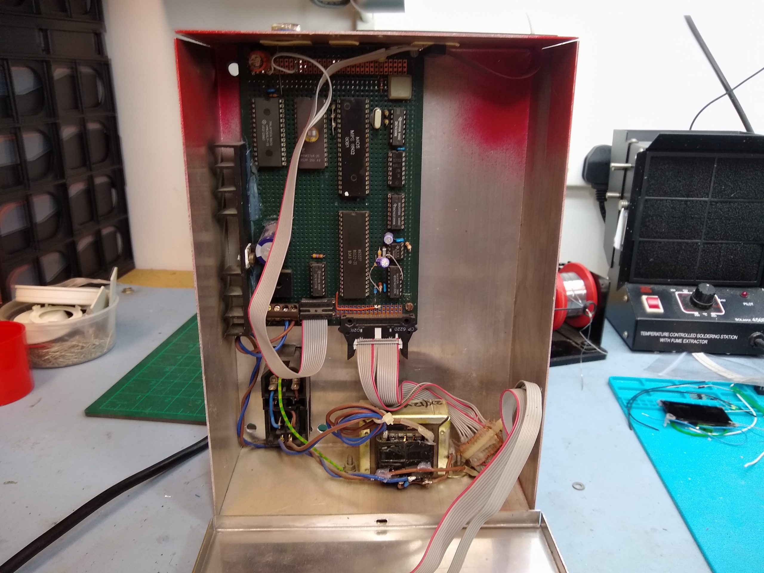
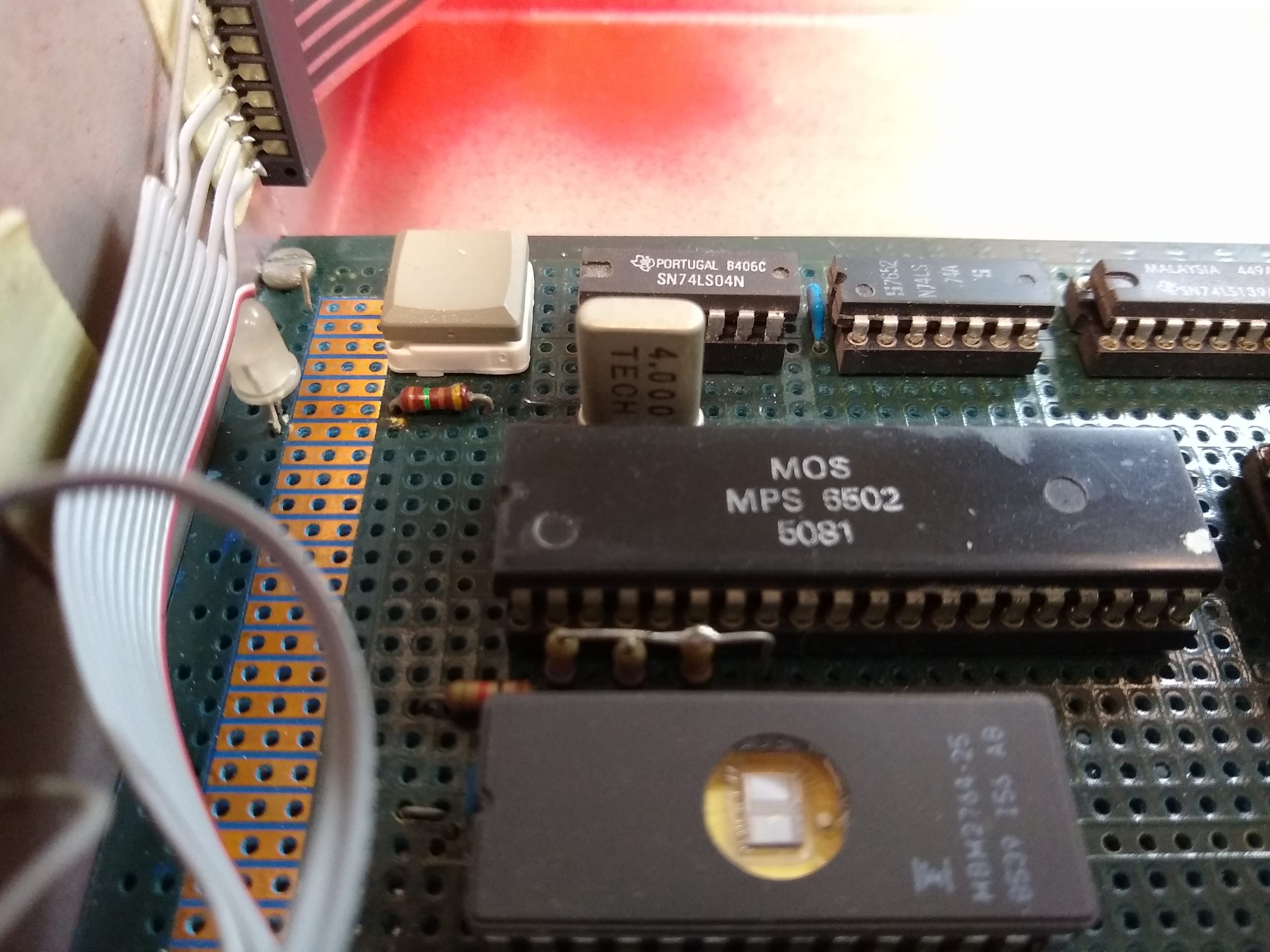
The code was written in machine code – I didn’t have an assembler so I wrote the code by hand on paper – entered the HEX opcodes and used a disassembler to check branches and jumps went were I intended. I could work out relative branch offsets in my head at the time. I also knew most of the opcode HEX values from the top of my head. To this day I know that $4C is JMP absolute, $A9 is LDA immediate, $EA is NOP.
It still works, so the EPROM has not given up its data in 36 years. The EPROM programmer was something I built myself and again wrote the code to control it.
Back when this was built sourcing parts and components involved a printed paper catalogue, a hand written order form posted to the supplier, or by 1986 perhaps a phone call followed by a wait for the order to be delivered, and generally no next-day shipping either. Also I was young and didn’t have a lot of money so parts tended to get robbed from one project to build the next.
In May 2019 I started working on the Record Clock Redux project and I actually completed the code, milled out the acrylic backplate and genuine 7″ single record all ready to assemble into the final clock. However, things happened and it never got finished, in fact I have barely touched a soldering iron, or done anything PIC micro related since.
Anyway, I sat in the workshop in the middle of December 2021 and put the pieces on the workbench. I looked over them trying to recall how I’d intended it to fit together and I decided this was the time (pun intended) to finish “Record Clock Redux“.
Final Assembly
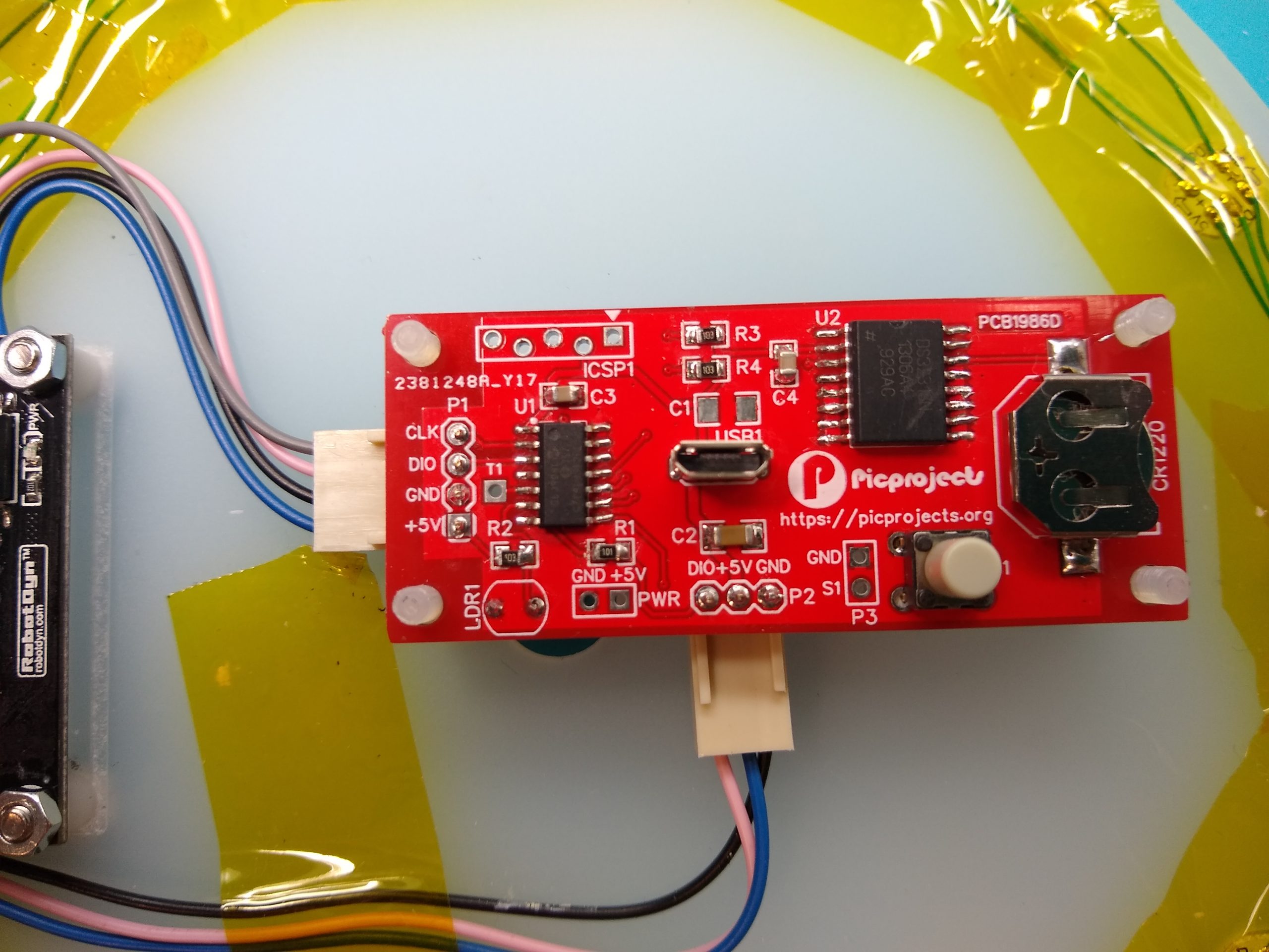
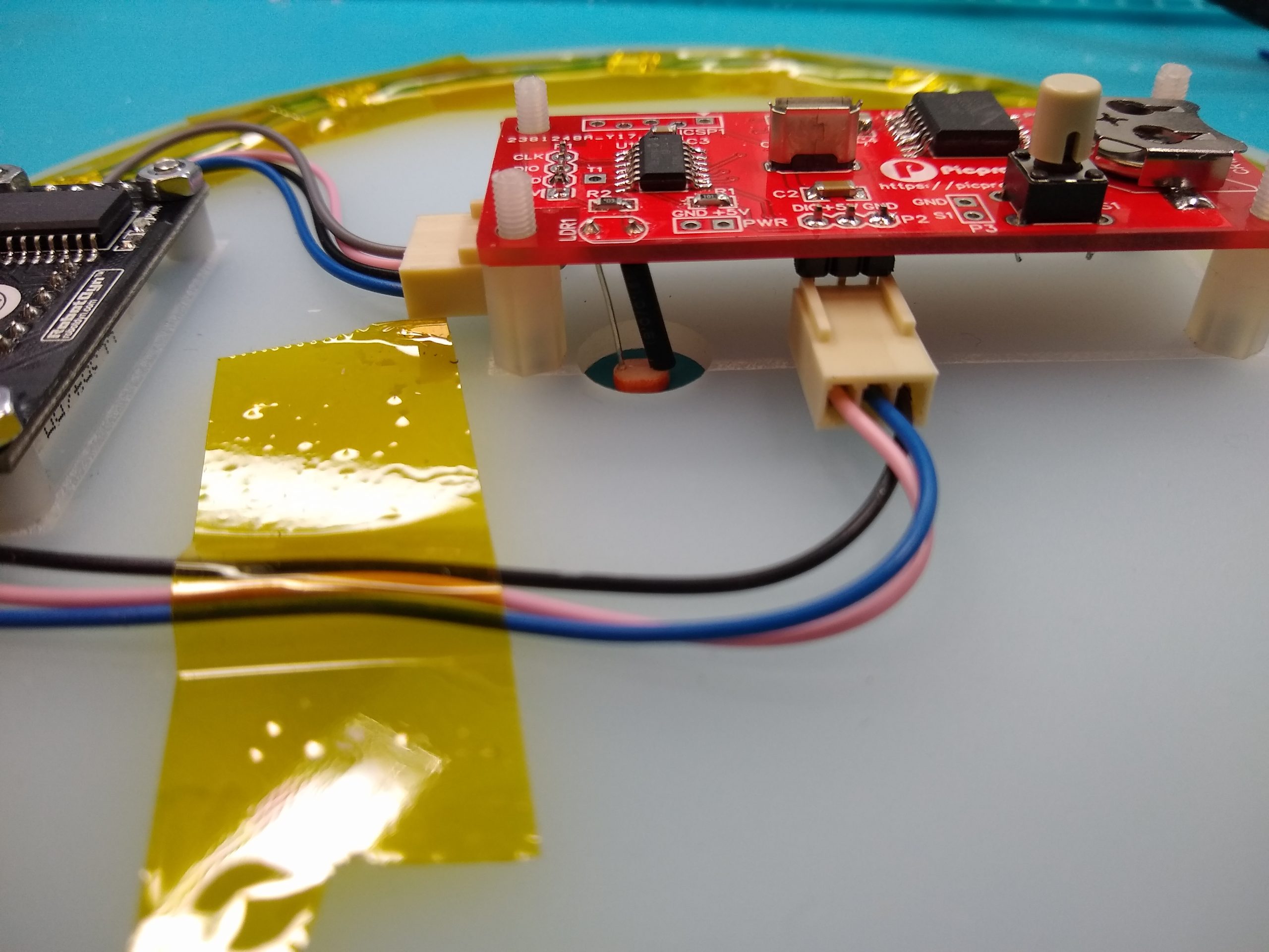
First problem I ran into was not having any PIC16F18325 microcontrollers in SOIC package. I checked my previous sources and no-stock until March/April 2022 so not a good start. At this point I could see how this might turn into another two years. Determined that I wasn’t leaving the workshop until it was finished I took a previous prototype PCB I had lying around and de-soldered the PIC for reuse. The control PCB was duly assembled, PIC programmed, battery installed and an initial test showed all was good.
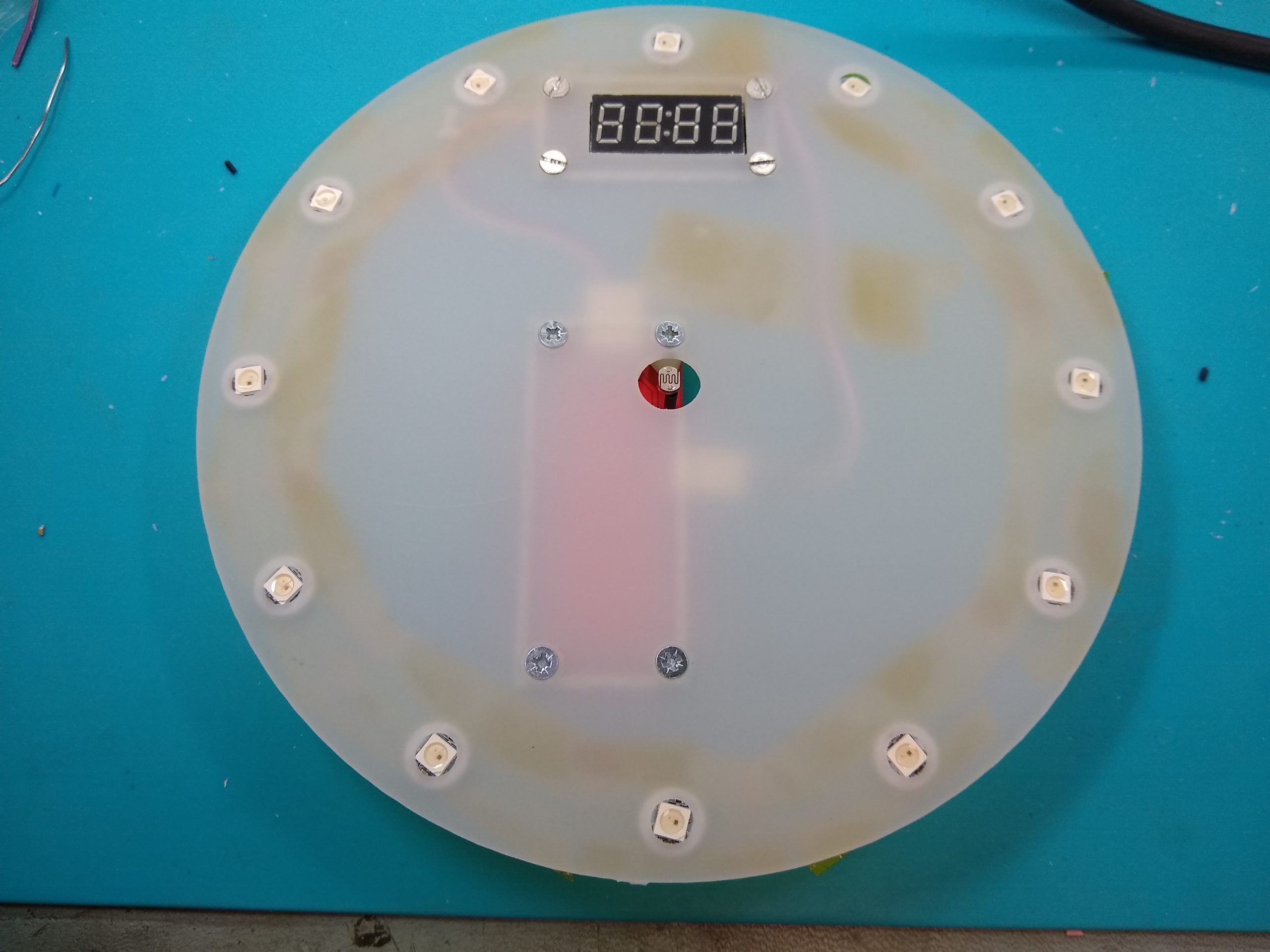
The acrylic backplate and the vinyl record had been milled out on my CNC3018 router two years previously along with the smoked acrylic ‘windows‘ for the LEDs. A little reaming and counter sinking of the holes for the PCB mounting screws was all that was left to do here.
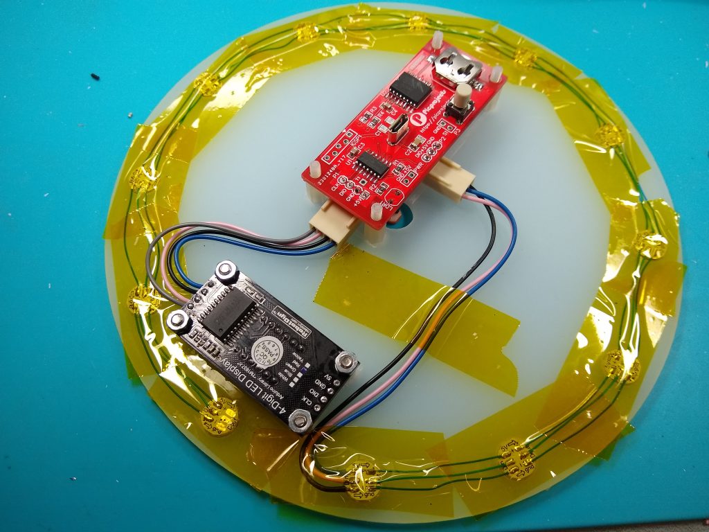
Next was the installation of the WS2812 RGB LED modules. I previously bought a large array of these pre-soldered onto small PCBs. I linked these together with Kynar wire then made up a short lead with 0.1″ Molex connector to the PCB. The LEDs and wiring were held in place using Kapton tape. I did this rather than gluing them in place to make it easier to fix any issues with the modules or wiring. As it turns out there weren’t any. The 7 segment display is a 0.37″ RobotDyn module using a TM1637 control IC.
To fix the 7″ single record to the acrylic backplate, I drilled a couple of 5mm holes in the backplate then positioned and aligned the record over the front and clamped it in place. The record is spaced off the back plate about 1mm, this allowed me to inject hot-melt glue through the 5mm holes which then stuck them together. It’s still possible to separate them if needed by sliding a knife inbetween the backplate and record; I know, I have done it 🙂
In retrospect I wish I had used some WS2812 LEDs in a 5mm round opaque package. This would have been true to the original and I hope diffuse the light better than the 5050 SMD parts. In fact I have aquired some and may yet build a redux V2 clock – maybe 😉
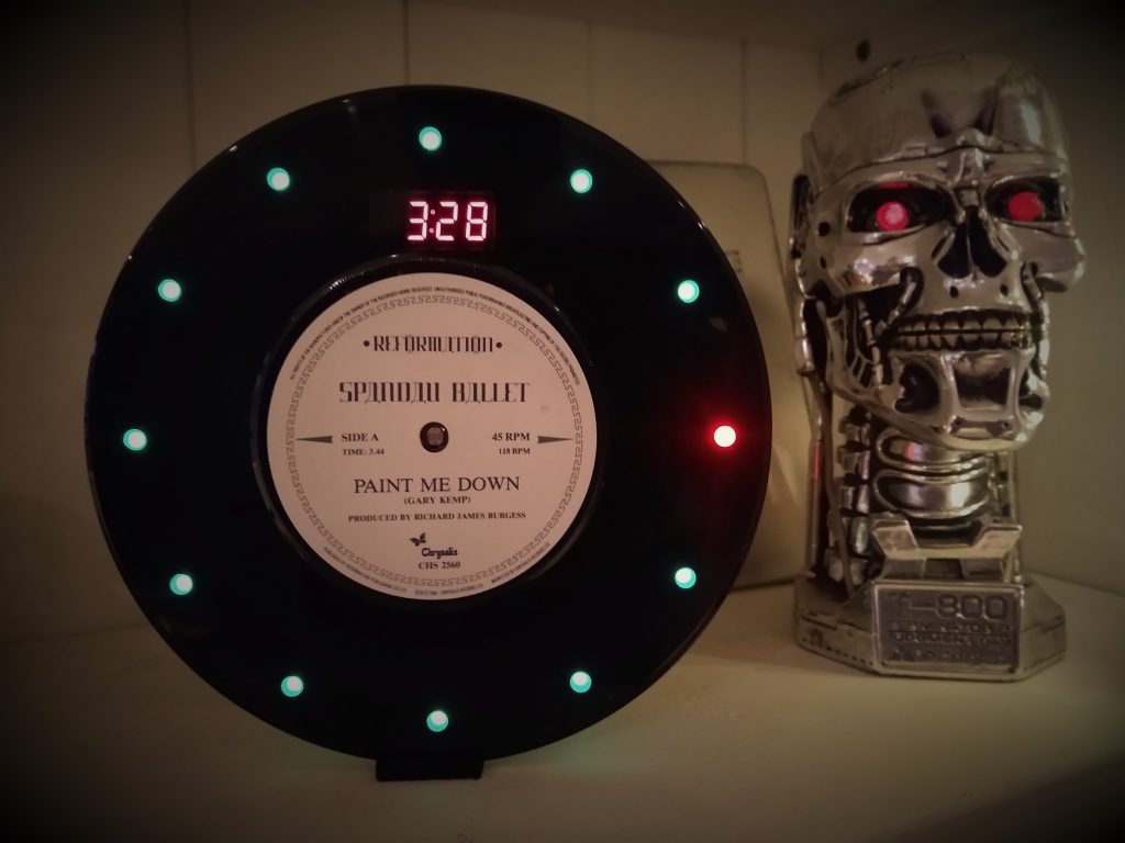
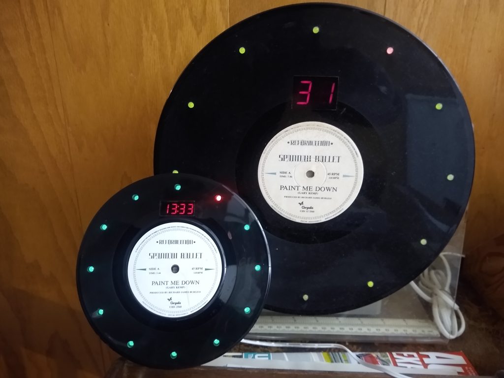
Original and Redux
It’s now 36 years since I made the original 12″ version of the clock. Ever since I started messing around with PIC microcontrollers it has been something I have always had in the back of my mind as a project I should do again. I’d kind of expected the original clock to die at some point and then I’d have a reason to do it, but amazingly its run 24/7 since 1986. Apart from a repair due to overzealous dusting breaking a wire to an LED, it just keeps going. It would be interesting to see if the PIC version lasts as long, not that I’ll be around to see that – 😨
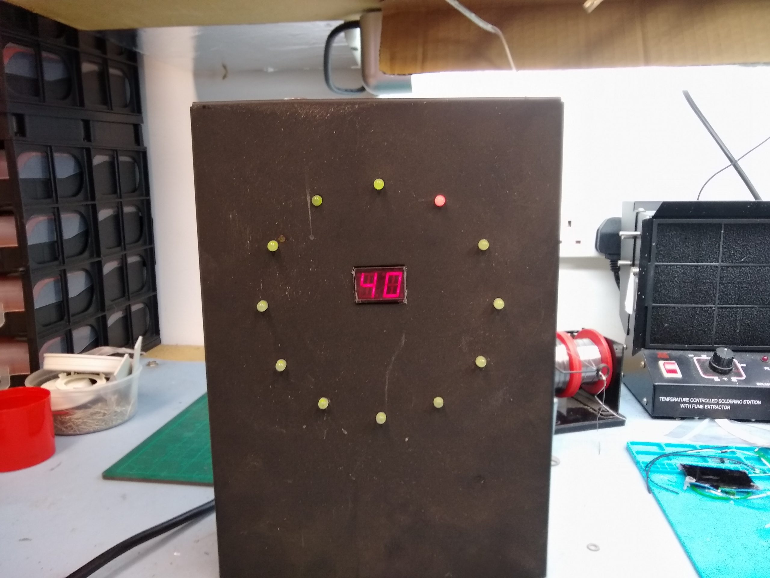
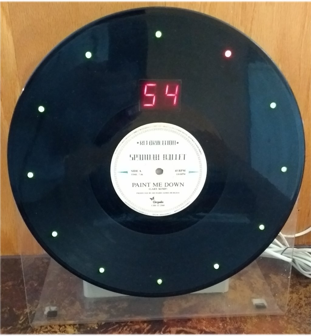
So the photo below shows the original and redux clocks together for comparison. The original only displays the minutes on the 7-segment LEDs, while the new version using the 4-digit display shows hours and minutes, or minutes and seconds as well as the option to display temperature. One thing the original does better is the dimming of the display. The TM1637 has brightness control but it is in discrete steps, so the new verison has three stepped levels of brightness while the original does a pleasing PWM fade.
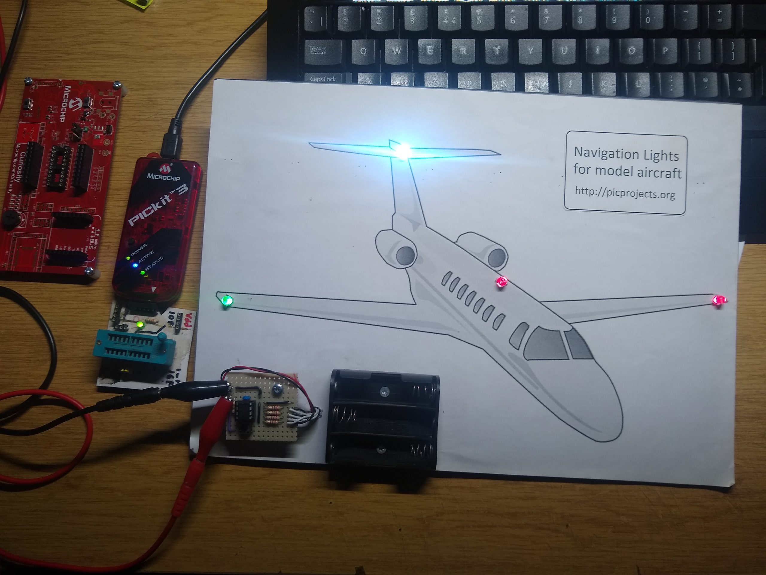
Recently I needed to revist the code for a project I did back in 2012 Navigation Lights for Models. In doing so I discovered that the latest version of MPLAB X (5.45) has dropped the old MPASM assembler and the version of assembler now being used doesn’t play well with source code written for the old MPASM assembler. I still have MPLAB X IDE V5.30 installed with support for MPASM and this works fine.
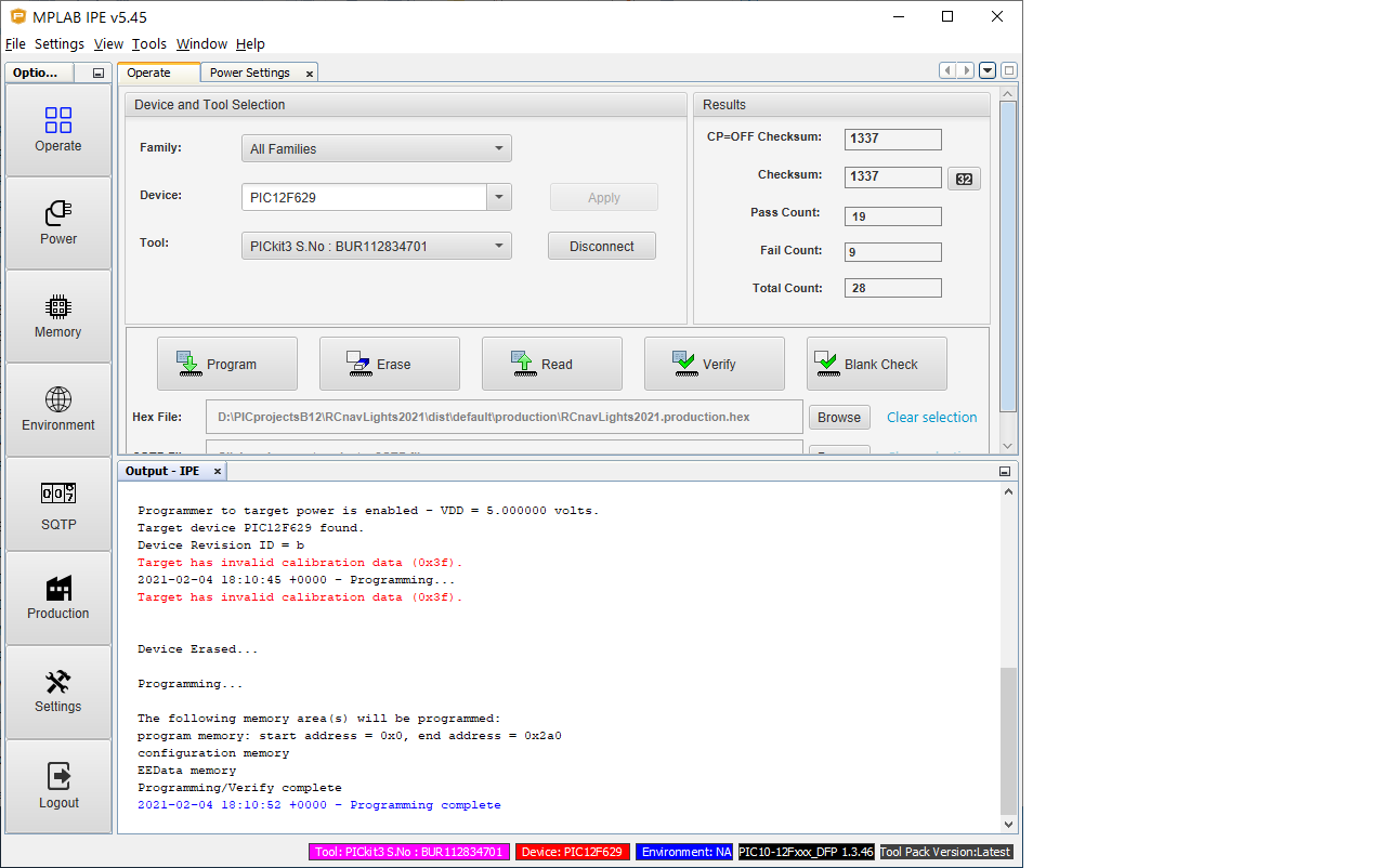
The reason I revisited this project was because over the years many people have contacted me having trouble getting it to work. A common cause is the calibration word in the PIC12F629 getting erased. Even I get caught out with it 🙁
Since the original code attempts to read the calibration word after power-on, if it’s not present the code just loops and the PIC appears to be dead. Since the timing is in no way critical for this application, I have reassembled the original code, skipping the bit that attempts to read the calibration word and instead writing a default 0x7F into the OSCCAL register of the 12F629/675. This way, it doesn’t matter if the calibration word gets erased or overwritten, the program will still happily run.
You can download the programmer ready HEX file for this new version below.
Way back in the 80’s – 1986 to be precise since I dated one of the PCBs – I made a ‘Record Time’ clock and it has lived in my parents kitchen ever since. Amazingly it’s still working 34 years later.
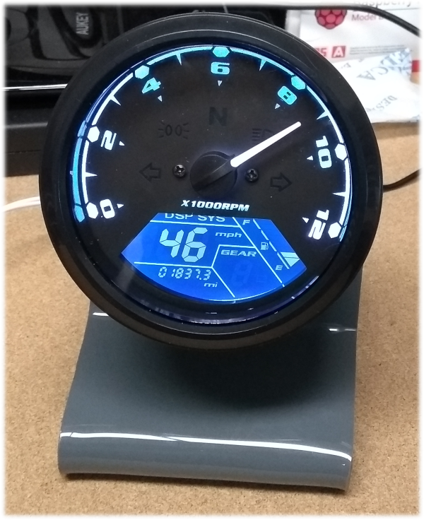
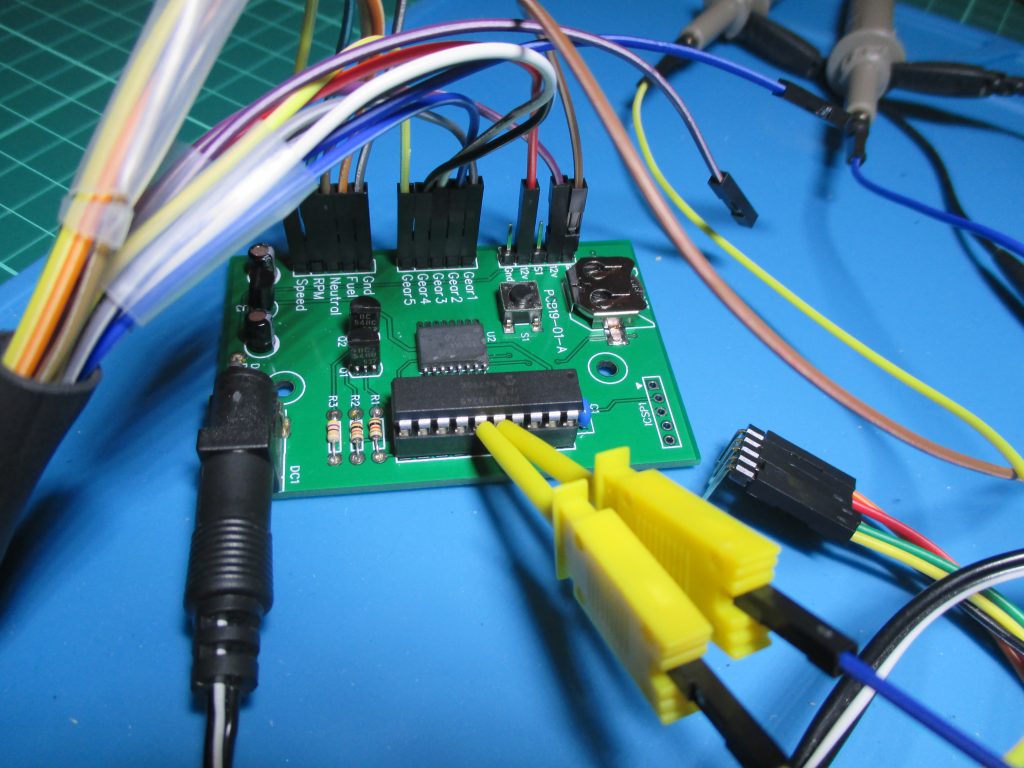
A few months ago I came across a post on the Hackaday website that showed a clock made using an instrument cluster for a motorbike. The clock featured in the article was based on an Arduino but I thought it would be interesting to do something similar using a PIC microcontroller. I had a look on eBay and found them being sold under the description of “Universal Motorcycle LCD Digital Speedometer Odometer Motorbike Tachometer Gauge”, or something similar and going for around £20.00
So I bought one and a few days later it arrived and the fun began…. Read all about it here
A couple of weeks back I decided to re-vist the F1 Gantry Race Start Lights project that I originally did back in 2009.
The new PCB has an extra header to make connection to relay modules easier and uses a double-sided PCB. It is functionaly the same as the original and uses the same firmware which is now free to download.
This is just a quick update to say I’ve been working on this steadily for the last few weeks. The PCB finally arrived earlier this week and I’ve got a board assembled and working.
This project is proving somewhat of a challenge. I’ve now bought two Universal LCD instrument clusters to test with and this is where things got interesting.
The second one I bought came without any instructions, I contacted the seller and they said sorry, we don’t have instructions for it. Now you might ask why did I need instructions for this one if I’d already got one? The answer is that while they look identical, the second unit is different, you enter setup mode in a different way, it configures differently although it has the same options and the 20 pin connector on the back of the unit is wired completely differently. The four connectors on the other end are wired the same but I’d bought some 20 pin connectors so I could make my own connector cable up. This second unit also seems to be more consistent at converting speed to minutes compared to the other one.
Anyway, I’m just working through what I hope are the last few little issues and a more detailed write up is coming…
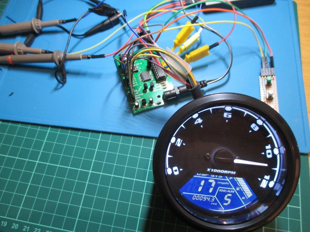
I recently saw a feature on the Hackaday website for a clock that had been made from a multifunction instrument cluster using the analogue tachometer for the hours and digital speed readout for minutes. This was implemented using an Arduino, so I thought perhaps I could do something using a PIC. I found the gauges on eBay, they’re usually described something like “LCD Digital Motorcycle Speedometer” and sell for around 20GBP so I bought one to play with.
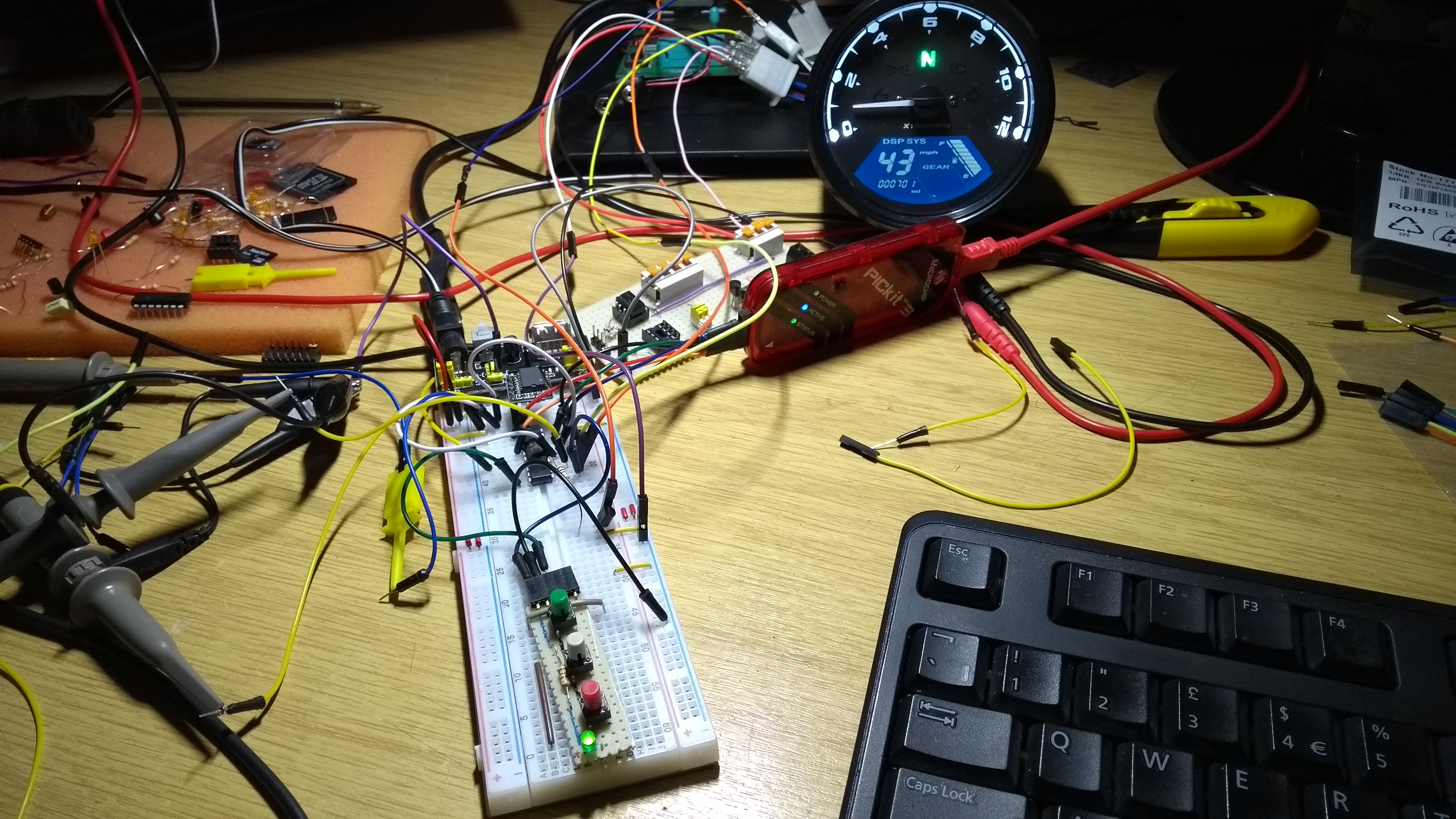
Development setup
Once I’d worked out what signals and voltages it required to operate I put things together on the breadboard with a PIC16F1823. Early on I figured it would need more I/O pins so got hold of some PIC16F18345 to work with.
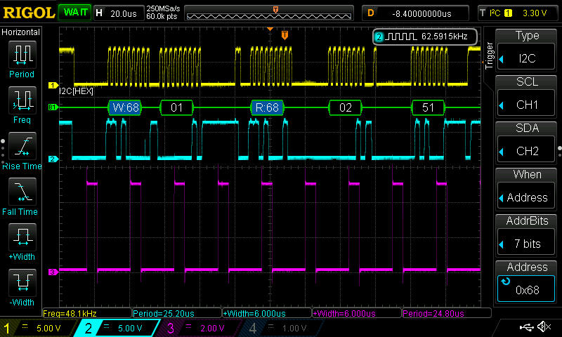
Reading the minutes and hours from DS3231 over I2C bus
For the actual time keeping I’ve used a DS3231 RTC. I found some really cheap modules on banggood.com, shipped from China. Three modules worked out cheaper than buying one from a UK distributor. I don’t know if they’re genuine parts or not but they certainly keep time accurately.
I’ve now got the software pretty much complete using Microchip XC8 C compiler and also a PCB designed and on order from JLC PCB. Once all the bits are together and working I’ll do an update here with all the code and other information.
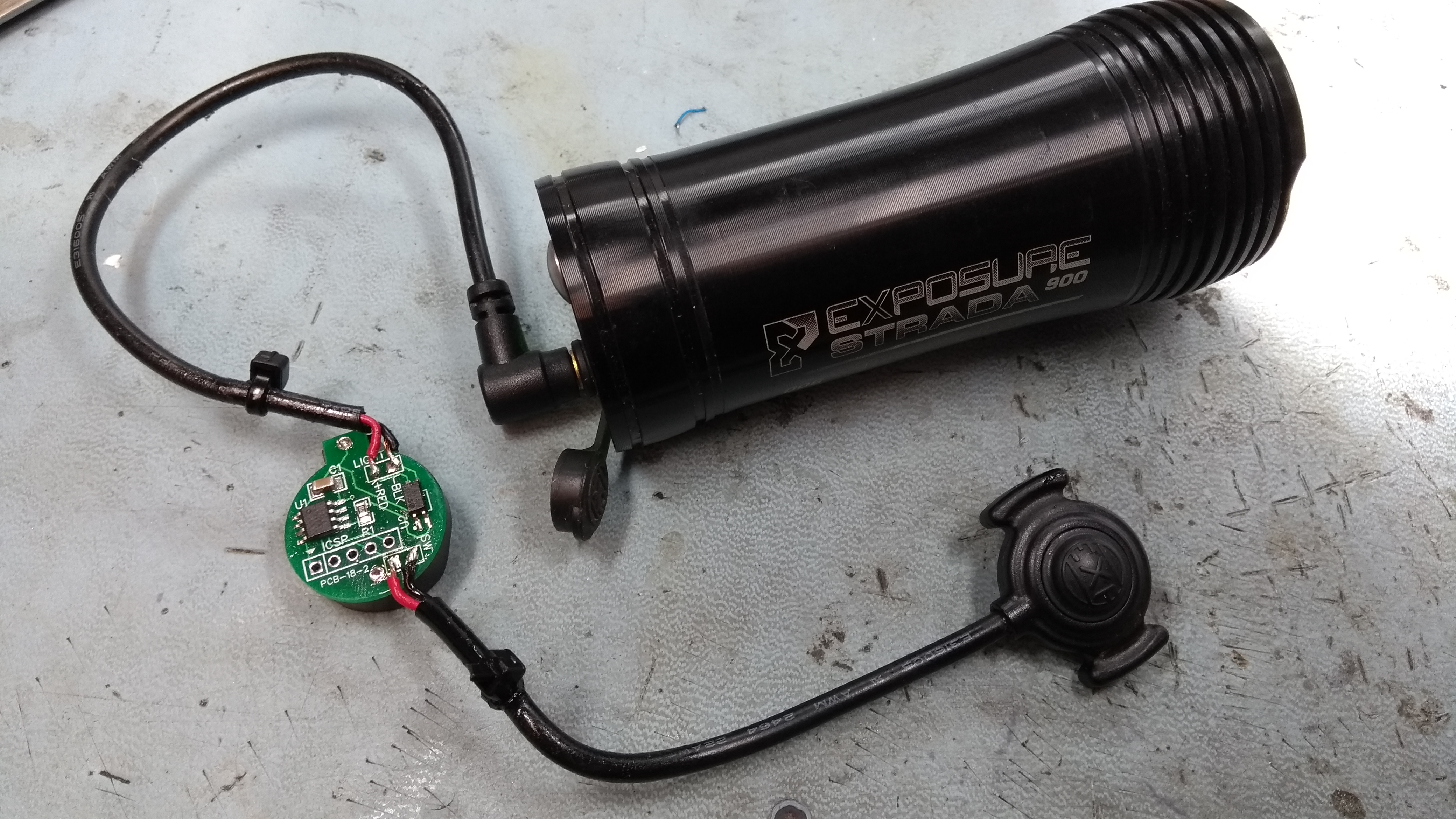
In mid December last year I put together a switch conditioner circuit to address the issue I had with the Exposure Strada light I was using on my MTB. I ran it on the bike until the end of March 2018 when the evenings had enough daylight not to need lights.
So how did it perform? The weather in the UK at the beginning of 2018 was cold, wet and even a couple of weeks of snow. Throughout the three months of use in the cold and rain it worked reliably. I had no more issues with either the switch not responding or going into flash mode, in a fact it eliminated all the issues I had previously. It’s still running on the CR2025 battery that was fitted in December and that battery wasn’t new.
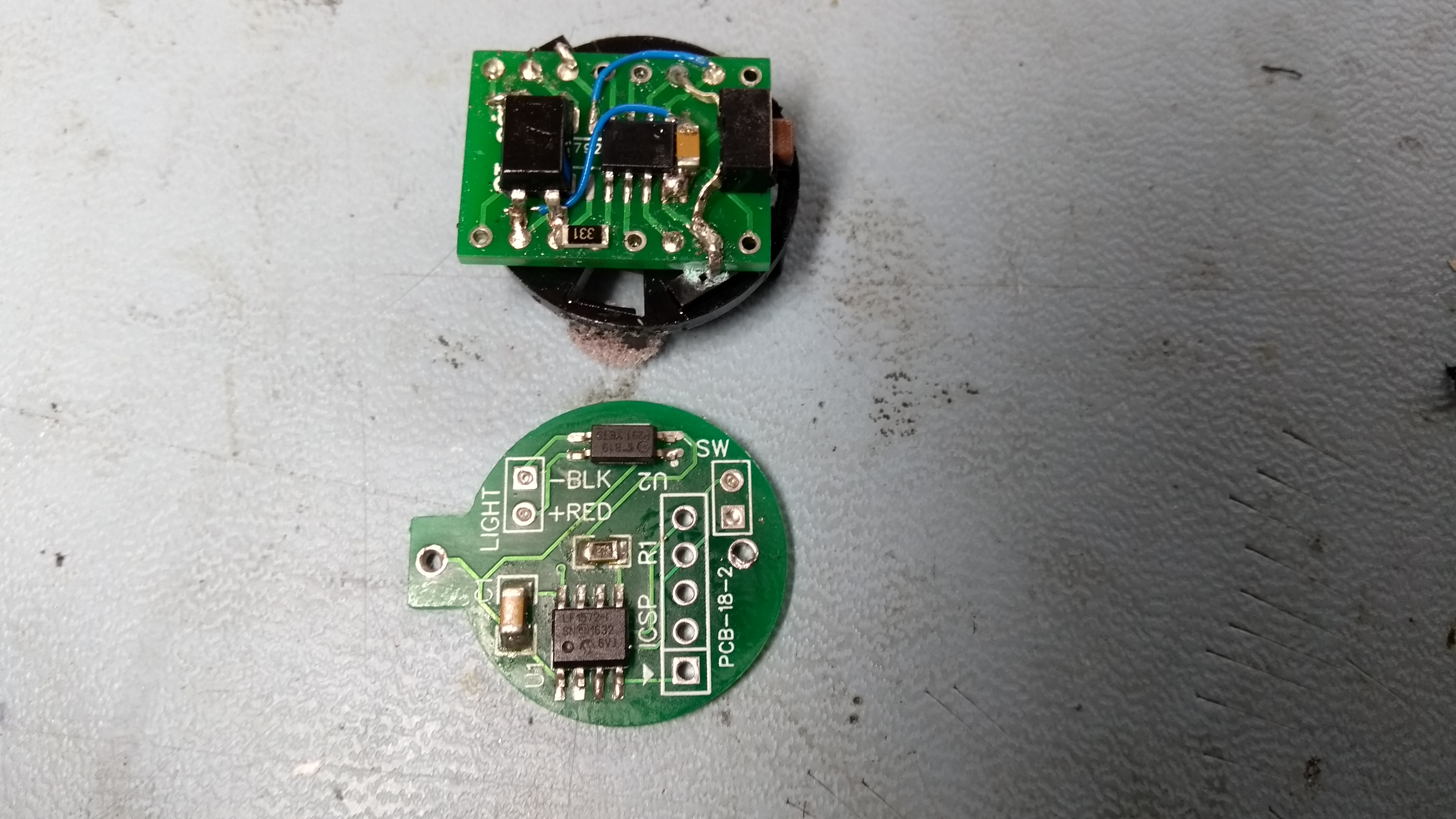
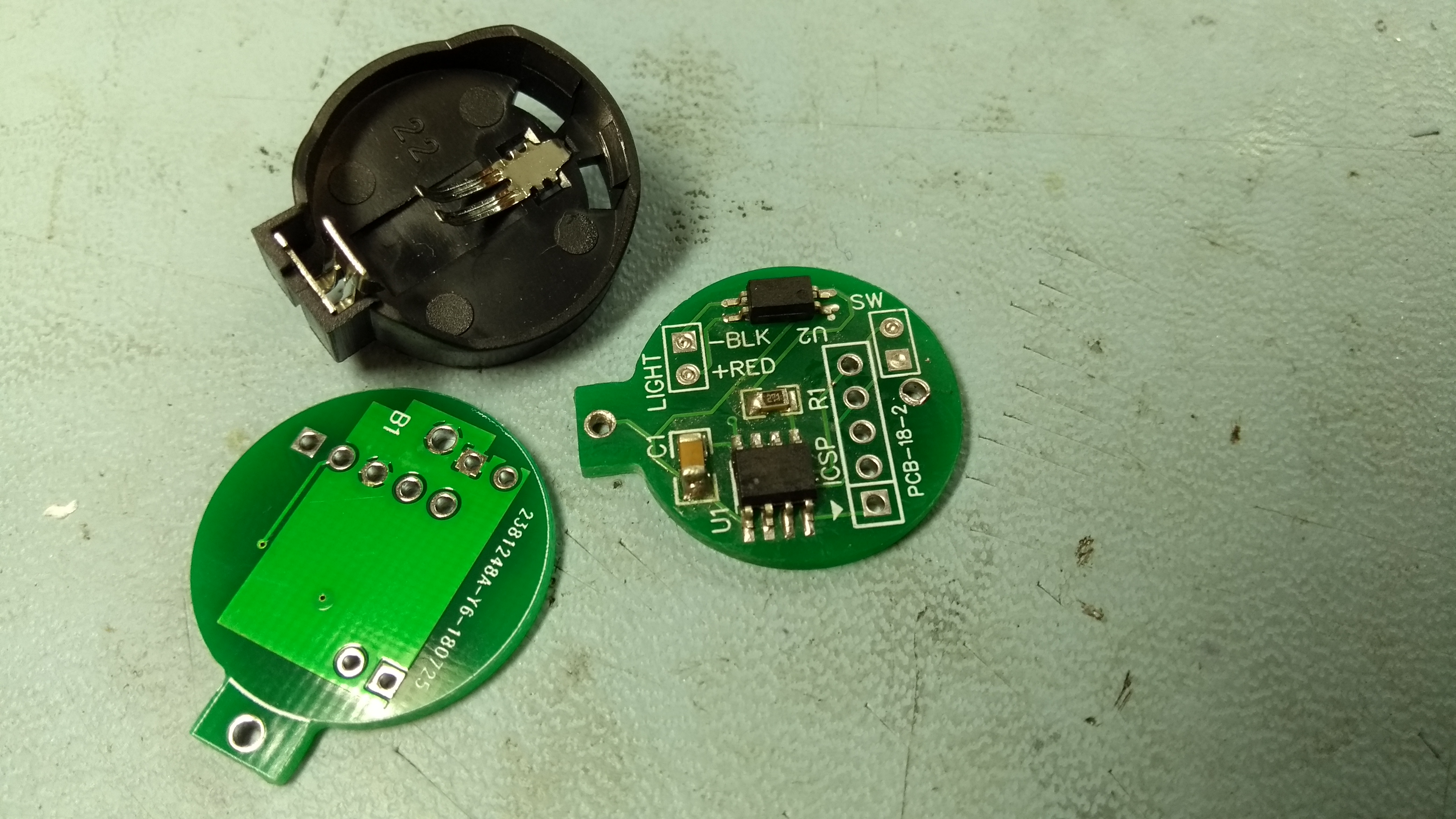
The original version was assembled on an SMD-to-DIP adapter PCB and was a bit of a hack. Since it worked so well I designed a PCB for it which has the same profile as the CR2025/2032 battery holder. The photo below shows the new PCB below next to the original hack. Since I had 10 boards made I assembled the first one for testing before making up a second to go on the bike.
The PCB was designed using EasyEDA and I had 10 boards manufactured by JLC PCB for $2 + shipping which worked out at about £6.00 for the boards shipped to the UK.
The new PCB has been profiled to fit under the coin cell battery holder and has an ICSP header so the PIC micro-controller can be programmed on the PCB.
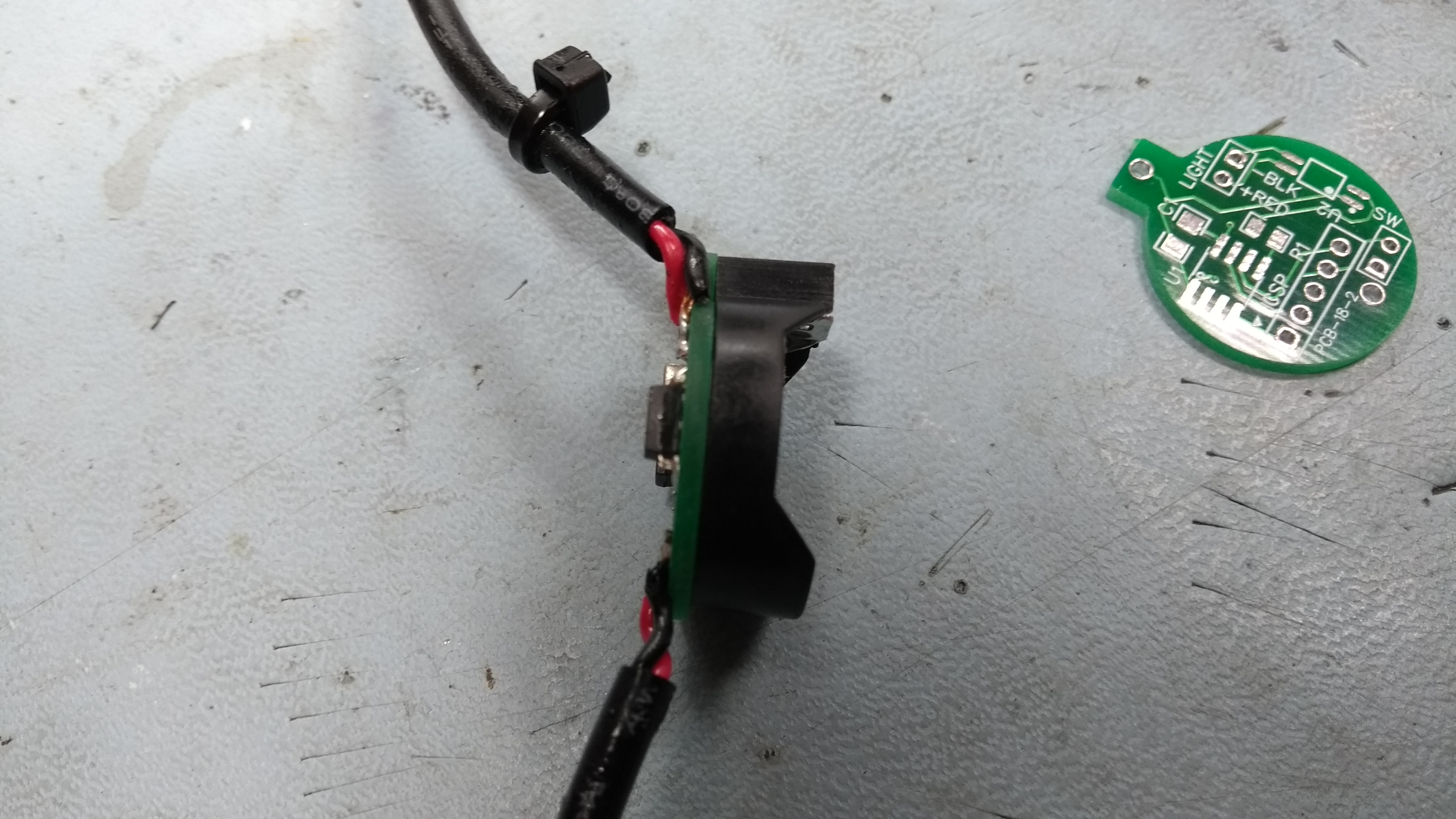
The assembled PCB was sprayed with conformal coating to protect from moisture and fitted into the same case I used for the original circuit. Cable ties provide strain relief, the pink foam stops it moving inside the case, and some silicone grease was used between the case and cover.
You can find the schematic and PCB Gerber files along with a link to order your own boards from JLC PCB below. The MPLABX source code and HEX firmware file is also available on the easyEDA site.